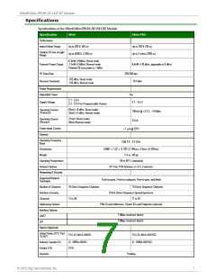
XBee®/XBee‐PRO® ZB SMT RF Modules
Electrical Specifications for GPIO Pads
GPIO Electrical Specification
Value
Output voltage for logic 1
0.82 x VCC (minimum)
Output source current for pad numbers 3, 4, 5, 10, 12, 14, 15,
16, 17, 25, 26, 28, 29, 30, and 32
4 mA
4 mA
Output source current for pad numbers 3, 4, 5, 10, 12, 14, 16,
17, 26, 28, 29, 30, and 33
Output source current for pad numbers 7, 8, 24, 31, and 33
Output sink current for pad numbers 7, 8, 24, 31, and 33
Total output current (for GPIO pads)
8 mA
8 mA
40 mA
Hardware Specs for Programmable Variant
If the module has the programmable secondary processor, add the following table values to the specifications
listed on page 7. For example, if the secondary processor is running at 20 MHz and the primary processor is in
recieve mode then the new current value will be Itotal = Ir2 + Irx = 14 mA + 9 mA = 23 mA, where Ir2 is the
runtime current of the secondary processor and Irx is the recieve current of the primary.
Specifications of the programmable secondary processor
These numbers add to specifications
Optional Secondary Processor Specification
(Add to RX, TX, and sleep currents depending on
mode of operation)
Runtime current for 32k running at 20MHz
Runtime current for 32k running at 1MHz
Sleep current
+14mA
+1mA
+0.5A typical
For additional specifications see Freescale Datasheet and
Manual
MC9SO8QE32
Minimum Reset low pulse time for EM357
VREF Range
+26S
1.8VDC to VCC
© 2010 Digi International, Inc.
9

 DCD [ DIGITAL CORE DESIGN ]