XBee®/XBee‐PRO® ZB SMT RF Modules
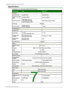
Specifications of the XBee®/XBee‐PRO® ZB SMT RF Module
Specification XBee
XBee-PRO
Japan
RoHS
Pending
Compliant
Serial Communications Specifications
XBee RF modules support both UART (Universal Asynchronous Receiver / Transmitter) and SPI (Serial
Peripheral Interface) serial connections.
UART
The SC1 (Serial Communication Port 1) of the Ember 357 is connected to the UART port.
UART Pin Assignments
UART Pins
DOUT
Module Pin Number
3
4
DIN / CONFIG
CTS / DIO7
RTS / DIO6
25
29
More information on UART operation is found in the UART section in Chapter 2.
SPI
The SC2 (Serial Communication Port 2) of the Ember 357 is connected to the SPI port.
SPI Pin Assignments
SPI Pins
Module Pin Number
SPI_SCLK / DIO18
SPI_SSEL / DIO17
SPI_MOSI / DIO16
SPI_MISO / DIO15
14
15
16
17
For more information on SPI operation, see the SPI section in Chapter 2.
GPIO Specifications
XBee RF modules have 15 GPIO (General Purpose Input / Output) ports available. The exact list will depend
on the module configuration, as some GPIO pads are used for purposes such as serial communication.
See GPIO section for more information on configuring and using GPIO ports.
Electrical Specifications for GPIO Pads
GPIO Electrical Specification
Voltage - Supply
Value
2.1 - 3.6 V
Low Schmitt switching threshold
High Schmitt switching threshold
Input current for logic 0
0.42 - 0.5 x VCC
0.62 - 0.8 x VCC
-0.5 A
Input current for logic 1
0.5 A
Input pull-up resistor value
Input pull-down resistor value
Output voltage for logic 0
29 k
29 k
0.18 x VCC (maximum)
© 2010 Digi International, Inc.
8

 DCD [ DIGITAL CORE DESIGN ]