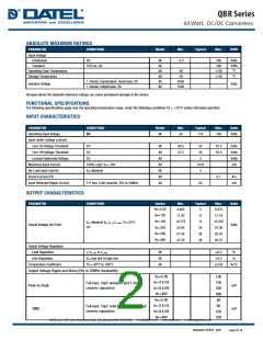
ABSOLUTE MAXIMUM RATINGS
Units
PARAMETER
CONDITIONS
Model
Min.
Typical
Max.
Input Voltage
Volts
Volts
°C
Continuous
DC
All
All
All
All
All
All
-0.3
160
180
Transient
100 ms, DC
Operating Case Temperature
Storage Temperature
-40
-55
+105
+125
°C
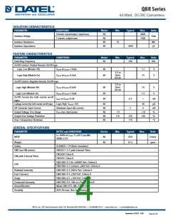
1 minute; input/output, input/case, DC
1 minute; output/case, DC
3000
1500
Volts
Isolation Voltage
Stresses above the absolute maximum ratings can cause permanent damage to the device.
FUNCTIONAL SPECIFICATIONS
The following specifications apply over the operating temperature range, under the following conditions TA = +25°C unless otherwise specified
INPUT CHARACTERISTICS
PARAMETER
CONDITIONS
DC
Model
Min.
Typical
Max.
Units
Operating Input Voltage
Input Under-voltage Lockout
Turn-On Voltage Threshold
Turn-Off Voltage Threshold
Lockout Hysteresis Voltage
Maximum Input Current
No-Load Input Current
Inrush Current (I2t)
All
43
110
160
Volts
DC
All
All
All
All
All
All
All
40.5
37.5
42
38
3
42.5
39.5
Volts
Volts
Volts
mA
DC
DC
100% Load, Vin= 43V
Vin=Nominal
1570
5
0.1
A2s
mA
Input Reflected Ripple Current
P-P thru 12µH inductor, 5Hz to 20MHz
30
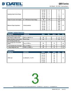
OUTPUT CHARACTERISTICS
PARAMETER
CONDITIONS
Device
Min.
4.925
11.82
14.775
23.64
27.58
47.28
Typical
5
Max.
5.075
12.18
15.225
24.36
28.42
48.72
Units
Vo=5.0V
Vo=12V
Vo=15V
Vo=24V
Vo=28V
Vo=48V
12
15
Vin=Nominal Vin, Io = Io_max, Tc=25°C
DC
Output Voltage Set Point
Volts
24
28
48
Output Voltage Regulation
Load Regulation
Io=Io_min to Io_max
All
All
All
0.2
0.2
%
%
Line Regulation
Vin=low line to high line
TC=-40°C to 100°C
Temperature Coefficient
0.03
%/°C
Output Voltage Ripple and Noise (5Hz to 20MHz bandwidth)
Vo=5.0V
Vo=12 & 15V
Vo=24 & 28V
Vo=48V
100
150
240
480
40
Full load, 10µF tantalum and 1.0uF
ceramic capacitors
Peak-to-Peak
mV
Vo=5.0V
Vo=12 & 15V
Vo=24 & 28V
Vo=48V
60
Full load, 10µF solid tantalum and 1.0µF
ceramic capacitors
RMS
mV
100
200
September 18 2017 B.03
Page 2 of 15

 DATEL [ DATEL, Inc. ]