DS1921H/Z
PARAMETER
SYMBOL
CONDITIONS
MIN
TYP MAX UNITS NOTES
IO pin, 1-Wire Reset, Presence Detect Cycle
Reset Low Time
tRSTL
Standard Speed,
VPUP > 4.5V
480
640
µs
1, 15
Standard Speed
Overdrive Speed
Standard Speed
Overdrive Speed
Standard Speed
Overdrive Speed
Standard Speed
Overdrive Speed
540
48
15
1.1
60
7.5
60
6
640
80
60
6
270
24
75
8.6
Presence Detect High
Time
Presence Detect Low
Time
Presence Detect
Sample Time
tPDH
tPDL
tMSP
µs
µs
µs
15
15
1, 16
IO pin, 1-Wire Write
Write-0 Low Time
tW0L
tW1L
Standard Speed
Overdrive Speed
Standard Speed
Overdrive Speed
60
6
5
120
15
15 - ε
2 - ε
µs
µs
1, 15
1, 11
Write-1 Low Time
1
IO pin, 1-Wire Read
Read Low Time
tRL
Standard Speed
Overdrive Speed
Standard Speed
Overdrive Speed
5
1
µs
µs
1, 12
1, 12
15 - δ
2 - δ
15
Read Sample Time
tMSR
tRL + δ
tRL + δ
2
Real-Time Clock
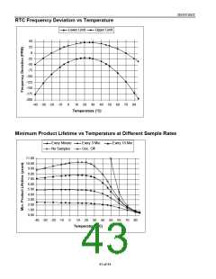
Frequency Deviation
Temperature Converter
Tempcore Operating
Range
Conversion Time
Thermal Response
Time Constant
-5°C to +46°C
-48
+46
PPM
°C
∆
F
TTC
DS1921H
DS1921Z
15
-5
75
46
+26
360
tCONV
τRESP
ms
s
130
13
Conversion Error
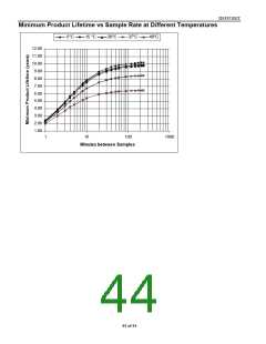
Number of
Conversions
-1
+1
°C
—
17, 18
14, 16
∆ϑ
NCONV
(see graphs)
NOTES
1) System Requirement.
2) Maximum allowable pull-up resistance is a function of the number of 1-Wire devices in the
system and 1-Wire recovery times. The specified value here applies to systems with only one
device and with the minimum 1-Wire recovery times. For more heavily loaded systems, an active
pull-up such as that found in the DS2480B may be required.
3)
Capacitance on IO could be 800pF when power is first applied. If a 2.2kΩ resistor is used to pull
up the data line, 2.5µs after VPUP has been applied the parasite capacitor will not affect normal
communication.
4) Input load is to ground.
5) All voltages are referenced to ground.
6) VTL, VTH are a function of the internal supply voltage.
7) Voltage below which, during a falling edge on IO, a logic 0 is detected.
8) The voltage on IO needs to be less or equal to VILMAX whenever the master drives the line low.
41 of 44

 DALLAS [ DALLAS SEMICONDUCTOR ]