DS1921H/Z
CRC GENERATION
With the DS1921H/Z there are two different types of Cyclic Redundancy Checks (CRCs). One CRC is an
8-bit type and is stored in the most significant byte of the 64-bit ROM. The bus master can compute a
CRC value from the first 56 bits of the 64-bit ROM and compare it to the value stored within the
DS1921H/Z to determine if the ROM data has been received error-free. The equivalent polynomial
function of this CRC is X8 + X5 + X4 + 1. This 8-bit CRC is received in the true (noninverted) form. It is
computed at the factory and lasered into the ROM.
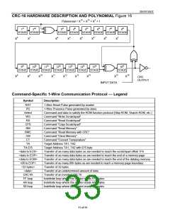
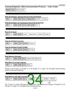
The other CRC is a 16-bit type, generated according to the standardized CRC16-polynomial function X16
+ X15 + X2 + 1. This CRC is used for error detection when reading data memory using the Read Memory
with CRC command and for fast verification of a data transfer when writing to or reading from the
scratchpad. In contrast to the 8-bit CRC, the 16-bit CRC is always communicated in the inverted form. A
CRC-generator inside the DS1921H/Z chip (Figure 16) will calculate a new 16-bit CRC as shown in the
command flow chart of Figure 10. The bus master compares the CRC value read from the device to the
one it calculates from the data and decides whether to continue with an operation or to reread the portion
of the data with the CRC error. With the initial pass through the Read Memory with CRC flow chart, the
16-bit CRC value is the result of shifting the command byte into the cleared CRC generator, followed by
the 2 address bytes and the data bytes. Subsequent passes through the Read Memory with CRC flow chart
will generate a 16-bit CRC that is the result of clearing the CRC generator and then shifting in the data
bytes.
With the Write Scratchpad command the CRC is generated by first clearing the CRC generator and then
shifting in the command code, the target addresses TA1 and TA2 and all the data bytes. The DS1921H/Z
will transmit this CRC only if the data bytes written to the scratchpad include scratchpad ending offset
11111b. The data may start at any location within the scratchpad.
With the Read Scratchpad command the CRC is generated by first clearing the CRC generator and then
shifting in the command code, the target addresses (TA1 and TA2), the E/S byte, and the scratchpad data
starting at the target address. The DS1921H/Z will transmit this CRC only if the reading continues
through the end of the scratchpad, regardless of the actual ending offset.
For more information on generating CRC values see Application Note 27 or the Book of DS19xx iButton
Standards.
32 of 44

 DALLAS [ DALLAS SEMICONDUCTOR ]