DS1921H/Z
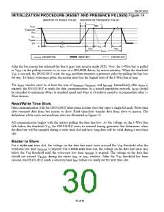
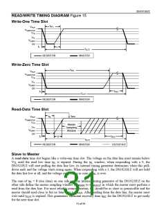
READ/WRITE TIMING DIAGRAM Figure 15
Write-One Time Slot
tW1L
VPUP
VIHMASTER
VTH
VTL
VILMAX
0V
tF
ε
tSLOT
RESISTOR
MASTER
Write-Zero Time Slot
tW0L
VPUP
VIHMASTER
VTH
VTL
VILMAX
0V
tF
tREC
tSLOT
RESISTOR
MASTER
Read-Data Time Slot
tMSR
tRL
VPUP
VIHMASTER
VTH
Master
Sampling
Window
VTL
VILMAX
0V
tF
tREC
δ
tSLOT
RESISTOR
MASTER
DS1921H/Z
Slave to Master
A read-data time slot begins like a write-one time slot. The voltage on the data line must remain below
VTL until the read low time tRL is expired. During the tRL window, when responding with a 0, the
DS1921H/Z will start pulling the data line low; its internal timing generator determines when this pull-
down ends and the voltage starts rising again. When responding with a 1, the DS1921H/Z will not hold
the data line low at all, and the voltage starts rising as soon as tRL is over.
The sum of tRL + δ (rise rime) on one side and the internal timing generator of the DS1921H/Z on the
other side define the master sampling window (tMSRMIN to tMSRMAX) in which the master must perform a
read from the data line. For most reliable communication, tRL should be as short as permissible and the
master should read close to but no later than tMSRMAX. After reading from the data line, the master must
wait until tSLOT is expired. This guarantees sufficient recovery time tREC for the DS1921H/Z to get ready
for the next time slot.
31 of 44

 DALLAS [ DALLAS SEMICONDUCTOR ]