DS1685/DS1687 3V/5V Real-Time Clocks
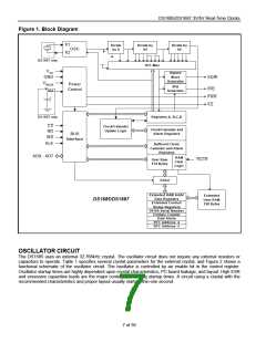
Figure 1. Block Diagram
X1
Divide
by 8
Divide by
64
Divide by
64
OSC
X2
DS1687 only
16:1 Mux
VCC
GND
VBAUX
VBAT
Square
Wave
SQW
Generator
IRQ
Generator
Power
Control
IRQ
PWR
KS
DS1687 only
Registers A, B,C,D
CS
RD
Clock/Calender
Update Logic
Clock/Calendar and
Alarm Registers
BUS
Interface
W R
ALE
Buffered Clock/
Calendar and Alarm
Registers
AD0 - AD7
RAM
User Ram
Clear
RLCR
114 Bytes
Logic
Select
Extended RAM Addr/
Data Registers
Extended
User RAM
128 Bytes
DS1685/DS1687
Extended Control/
Status Registers
64-Bit Serial Number
Century Counter
Date Alarm
RTC Address -2
RTC Address -3
OSCILLATOR CIRCUIT
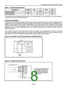
The DS1685 uses an external 32.768kHz crystal. The oscillator circuit does not require any external resistors or
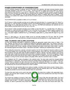
capacitors to operate. Table 1 specifies several crystal parameters for the external crystal, and Figure 2 shows a
functional schematic of the oscillator circuit. The oscillator is controlled by an enable bit in the control register.
Oscillator startup times are highly dependent upon crystal characteristics, PC board leakage, and layout. High ESR
and excessive capacitive loads are the major contributors to long startup times. A circuit using a crystal with the
recommended characteristics and proper layout usually starts within one second.
7 of 39

 DALLAS [ DALLAS SEMICONDUCTOR ]