DS1085
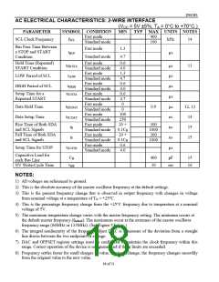
AC ELECTRICAL CHARACTERISTICS: 2-WIRE INTERFACE
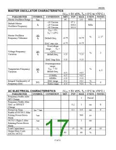
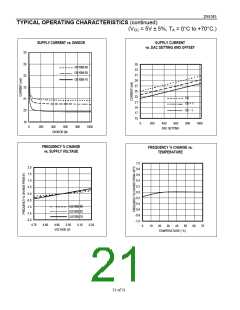
(VCC = 5V ±5%, TA = 0°C to +70°C.)
PARAMETER
SYMBOL CONDITION
MIN
TYP MAX UNITS NOTES
Fast mode
400
100
SCL Clock Frequency
fSCL
kHz
14
Standard mode
Bus Free Time Between
a STOP and START
Condition
Fast mode
1.3
4.7
tBUF
ꢁs
Standard mode
Hold Time (Repeated)
Fast mode
0.6
tHD:STA
11
ꢁs
ꢁs
ꢁs
ꢁs
ꢁs
ns
ns
ns
ꢁs
START Condition
Standard mode
4.0
Fast mode
1.3
LOW Period of SCL
HIGH Period of SCL
tLOW
Standard mode
4.7
Fast mode
0.6
tHIGH
Standard mode
4.0
Setup Time for a
Repeated START
tSU:STA
Fast mode
0.6
Standard mode
Fast mode
4.7
0
0
Data Hold Time
tHD:DAT
tSU:DAT
tR
0.9
12, 13
14
Standard mode
Fast mode
100
250
20 +
0.1CB
20 +
0.1CB
0.6
Data Setup Time
Standard mode
Fast mode
Rise Time of Both SDA
and SCL Signals
Fall Time of Both SDA
and SCL Signals
300
1000
300
15
Standard mode
Fast mode
tF
15
Standard mode
Fast mode
1000
Setup Time for STOP
tSU:STO
Standard mode
4.0
Capacitive Load for
each Bus Line
NV Write-Cycle Time
CB
400
10
pF
15
16
tWR
ms
NOTES:
1) All voltages are referenced to ground.
2) This is the absolute accuracy of the master oscillator frequency at the default settings.
3) This is the percent frequency change that is observed in output frequency with changes in voltage
from nominal voltage at a temperature of TA = +25LC.
4) This is the percentage frequency change from the +25°C frequency due to temperature at a nominal
voltage of 5V.
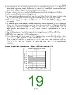
5) The maximum temperature change varies with the master frequency setting. The minimum occurs at
the default master frequency (fdefault). The maximums occur at the extremes of the master oscillator
frequency range (66MHz or 133MHz). (See Figure 5 below.)
6) The integral nonlinearity of the frequency adjust DAC is a measure of the deviation from a straight
line drawn between the two endpoints of a range.
7) DAC and OFFSET register settings must be configured to maintain the clock frequency within this
range. Correct operation of the device is not guaranteed if these limits are exceeded.
8) Frequency settles faster for small charges in value. During a change, the frequency changes smoothly
from the original value to the new value.
18 of 21

 DALLAS [ DALLAS SEMICONDUCTOR ]