CY8C21x34 Final Data Sheet
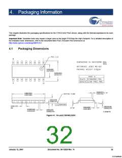
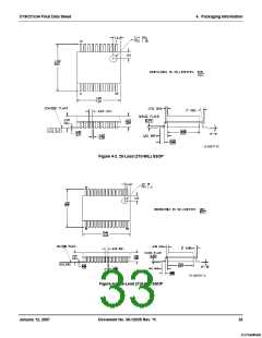
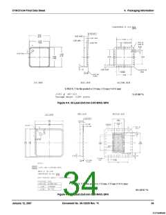
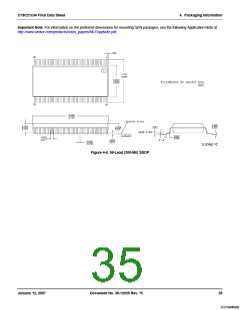
4. Packaging Information
4.2
Thermal Impedances
Table 4-1. Thermal Impedances per Package
Package
16 SOIC
Typical θJA
*
Typical θJC
o
o
123 C/W
55 C/W
o
o
20 SSOP
117 C/W
41 C/W
o
o
28 SSOP
96 C/W
39 C/W
o
o
32 QFN** 5x5 mm 0.60 MAX
32 QFN** 5x5 mm 0.93 MAX
* T = T + Power x θ
27 C/W
15 C/W
o
o
22 C/W
12 C/W
J
A
JA
** To achieve the thermal impedance specified for the QFN package, the center thermal pad should be soldered to the
PCB ground plane.
4.3
Solder Reflow Peak Temperature
Following is the minimum solder reflow peak temperature to achieve good solderability.
Table 4-2. Solder Reflow Peak Temperature
Package
Minimum Peak Temperature*
Maximum Peak Temperature
o
o
16 SOIC
240 C
260 C
o
o
20 SSOP
28 SSOP
32 QFN
240 C
260 C
o
o
240 C
260 C
o
o
240 C
260 C
o
*Higher temperatures may be required based on the solder melting point. Typical temperatures for solder are 220 ± 5 C
o
with Sn-Pb or 245 ± 5 C with Sn-Ag-Cu paste. Refer to the solder manufacturer specifications.
January 12, 2007
Document No. 38-12025 Rev. *K
36
[+] Feedback

 CYPRESS [ CYPRESS ]