CY7C68013A/CY7C68014A
CY7C68015A/CY7C68016A
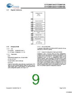
3.11
Register Addresses
FFFF
4 KBytes EP2-EP8
buffers
(8 x 512)
F000
EFFF
2 KBytes RESERVED
E800
E7FF
E7C0
64 Bytes EP1IN
E7BF
E780
E77F
E740
E73F
E700
E6FF
64 Bytes EP1OUT
64 Bytes EP0 IN/OUT
64 Bytes RESERVED
8051 Addressable Registers
(512)
E500
E4FF
E480
E47F
Reserved (128)
128 bytes GPIF Waveforms
Reserved (512)
E400
E3FF
E200
E1FF
512 bytes
8051 xdata RAM
E000
3.12.3 Set-up Data Buffer
3.12
Endpoint RAM
A separate 8-byte buffer at 0xE6B8-0xE6BF holds the Set-up
data from a CONTROL transfer.
3.12.1 Size
• 3× 64 bytes
(Endpoints 0 and 1)
3.12.4 Endpoint Configurations (High-speed Mode)
• 8 × 512 bytes (Endpoints 2, 4, 6, 8)
Endpoints 0 and 1 are the same for every configuration.
Endpoint 0 is the only CONTROL endpoint, and endpoint 1 can
be either BULK or INTERRUPT. The endpoint buffers can be
configured in any 1 of the 12 configurations shown in the
vertical columns. When operating in full-speed BULK mode
only the first 64 bytes of each buffer are used. For example in
high-speed, the max packet size is 512 bytes but in full-speed
it is 64 bytes. Even though a buffer is configured to be a 512
byte buffer, in full-speed only the first 64 bytes are used. The
unused endpoint buffer space is not available for other opera-
tions. An example endpoint configuration would be:
3.12.2 Organization
• EP0
• Bidirectional endpoint zero, 64-byte buffer
• EP1IN, EP1OUT
• 64-byte buffers, bulk or interrupt
• EP2,4,6,8
• Eight 512-byte buffers, bulk, interrupt, or isochronous. EP4
and EP8 can be double buffered, while EP2 and 6 can be
either double, triple, or quad buffered. For high-speed end-
point configuration options, see Figure 3-5.
Document #: 38-08032 Rev. *K
Page 9 of 60
[+] Feedback

 CYPRESS [ CYPRESS ]