BCM4330 Preliminary Data Sheet
Internal Regulator Electrical Specifications
Section 20: Internal Regulator Electrical
Specifications
Note: Values in this data sheet are design goals and are subject to change based on the results of
device characterization.
Functional operation is not guaranteed outside of the specification limits provided in this section.
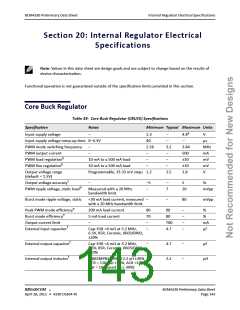
Core Buck Regulator
Table 39: Core Buck Regulator (CBUCK) Specifications
Specification
Notes
Minimum Typical Maximum Units
a
Input supply voltage
Input supply voltage ramp-up time 0–4.3V
PWM mode switching frequency
PWM output current
PWM load regulation
PWM line regulation
Output voltage range
(default = 1.5V)
Output voltage accuracy
PWM ripple voltage, static load
–
2.3
40
2.56
–
–
–
–
–
3.2
–
–
4.8
–
V
µs
–
–
3.84
500
±30
±10
1.8
MHz
mA
mV
mV
V
b
10 mA to a 500 mA load
10 mA to a 500 mA load
Programmable, 33.33 mV steps 1.2
b
–
1.5
c
–
–5
–
–
7
5
20
%
mVpp
d
Measured with a 20 MHz
bandwidth limit.
Burst mode ripple voltage, static
<30 mA load current, measured –
with a 20 MHz bandwidth limit.
–
80
mVpp
e
Peak PWM mode efficiency
Burst mode efficiency
200 mA load current
5 mA load current
–
80
70
–
90
80
700
4.7
–
–
–
–
%
%
mA
µF
e
Output current limit
External input capacitor
f
Cap–ESR <4 mΩ at 3.2 MHz,
6.3V, X5R, Ceramic, 0603/0402,
±20%
–
f
External output capacitor
Cap–ESR <4 mΩ at 3.2 MHz,
6.3V, X5R, Ceramic, 0603/0402,
±20%
–
4.7
2.2
–
–
µF
f
External output inductor
LQM2MPN2R2NG0 2.2 uH ±30% –
DCR = 110 mΩ ±25%, ACR <1Ω.
Isat = 1A (based on L-30%)
µH
®
BROADCOM
BCM4330 Preliminary Data Sheet
April 28, 2011 • 4330-DS304-RI
Page 143

 CYPRESS [ CYPRESS ]