BCM4330 Preliminary Data Sheet
Signal Assignments
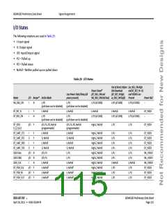
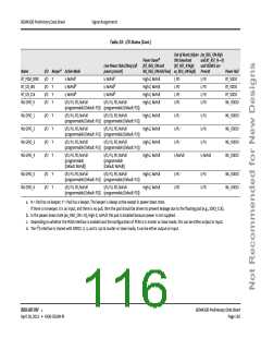
Table 23: I/O States (Cont.)
Out of Reset; Before (xx_REG_ON-high
Power Downb
(BT_REG_ON and
SW Download
and BT_RST_N = 0)
and VDDIOs are
Present
Low Power State/Sleep (all
power present)
I; NoPullc
I; NoPulld
I; NoPulld
(BT_RST_N high;
WL_REG_ON held low) xx_REG_ON high)
Name
I/O Keepera Active Mode
Power Rail
BT_VDDO
BT_VDDO
BT_VDDO
WL_VDDIO
BT_PCM_SYNC
BT_I2S_WS
BT_I2S_CLK
WL GPIO_0
I/O
I/O
I/O
I/O
Y
Y
Y
Y
I; NoPullc
I; NoPulld
I; NoPulld
High-Z, NoPull
High-Z, NoPull
High-Z, NoPull
High-Z, NoPull
I, PD
I, PD
I, PD
I; PD
I, PD
I, PD
I, PD
I; PD
I/O; PU, PD, NoPull
I/O; PU, PD, NoPull
(programmable [Default: PD]) (programmable [Default: PD])
WL GPIO_1
WL GPIO_2
WL GPIO_3
WL GPIO_4
I/O
I/O
I/O
I/O
Y
Y
Y
Y
I/O; PU, PD, NoPull
I/O; PU, PD, NoPull
High-Z, NoPull
High-Z, NoPull
High-Z, NoPull
High-Z, NoPull
I; PU
I; PU
WL_VDDIO
WL_VDDIO
WL_VDDIO
WL_VDDIO
(programmable [Default: PU]) (programmable [Default: PU])
I/O; PU, PD, NoPull I/O; PU, PD, NoPull
(programmable [Default: PU]) (programmable [Default: PU])
I/O; PU, PD, NoPull I/O; PU, PD, NoPull
(programmable [Default: PU]) (programmable [Default: PU])
I; PU
I; PU
I; PU
I; PU
I/O; PU, PD, NoPull
(programmable
[Default: NoPull])
I/O; PU, PD, NoPull
(programmable
[Default: NoPull])
I; NoPull
I; NoPull
WL GPIO_5
WL GPIO_6
I/O
I/O
Y
Y
I/O; PU, PD, NoPull
I/O; PU, PD, NoPull
High-Z, NoPull
High-Z, NoPull
I; PU
I; PD
I; PU
I; PD
WL_VDDIO
WL_VDDIO
(programmable [Default: PU]) (programmable [Default: PU])
I/O; PU, PD, NoPull
(programmable [Default: PD]) (programmable [Default: PD])
I/O; PU, PD, NoPull
a. N = Pad has no keeper; Y = Pad has a keeper. The keeper is always active except in power down state.
If there is no keeper, it is an input, and there is no pull, then the pad should be driven to prevent leakage due to the floating pad (e.g., SDIO_CLK).
b. In the power down state (xx_REG_ON = 0), High-Z; noPull: the pad is disabled because power is not supplied.
c. Depending on whether the PCM interface is enabled and the configuration of PCM is in master or slave mode, this can be either output or input.
2
d. The I S interface is shared with GPIO2, 3, 4, and 5. Up to master or slave mode, it can be either output or input.
BROADCOM
®
BCM4330 Preliminary Data Sheet
April 28, 2011 • 4330-DS304-RI
Page 116

 CYPRESS [ CYPRESS ]