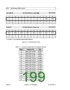
12.6 Port Configuration
PORTACFG
IO Port A Configuration
7F93
b7
b6
b5
b4
b3
b2
b1
b0
RxD1OUT RxD0OUT
FRD
FWR
CS
OE
T1OUT
T0OUT
R/W
0
R/W
0
R/W
0
R/W
0
R/W
0
R/W
0
R/W
0
R/W
0
PORTBCFG
IO Port B Configuration
7F94
b7
b6
b5
b4
b3
b2
b1
b0
T2OUT
INT6
INT5
INT4
TXD1
RXD1
T2EX
T2
R/W
0
R/W
0
R/W
0
R/W
0
R/W
0
R/W
0
R/W
0
R/W
0
PORTCCFG
IO Port C Configuration
7F95
b7
b6
b5
b4
b3
b2
b1
b0
RD
WR
T1
T0
INT1
INT0
TXD0
RXD0
R/W
0
R/W
0
R/W
0
R/W
0
R/W
0
R/W
0
R/W
0
R/W
0
Figure 12-6. IO Port Configuration Registers
These three registers control the three IO ports on the EZ-USB chip. They select between
IO ports and various alternate functions. They are read/write by the 8051.
When PORTnCFG=0, the port pin functions as IO, using the OUT, PINS, and OE control
bits. Data written to an OUTn registers appears on an IO Port pin if the corresponding
output enable bit (OEn) is HI.
When PORTnCFG=1, the pin assumes the alternate function shown in Table 12-4 on the
following page.
EZ-USB TRM v1.9
Chapter 12. EZ-USB Registers
Page 12-9

 CYPRESS [ CYPRESS ]