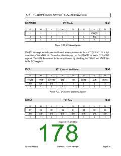
9.12 I2C Interrupt
EZ-USB 8051
EIE.1
8051 I2C
Interrupt
(INT3)
DONE
S
S
R
RD or WR
I2DAT register
EXIF.5(rd)
R
I2C Interrupt
Request
EXIF.5(0)
START
STOP
D6
LASTRD
D5
ID1
D4
ID0
D3
BERR
ACK
D1
DONE
I2CS
D7
D2
D0
I2DAT
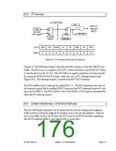
Figure 9-8. I2C Interrupt Enable Bits and Registers
Chapter 4, "EZ-USB Input/Output" describes the 8051 interface to the EZ-USB I2C con-
troller. The 8051 uses two registers, I2CS (I2C Control and Status) and I2DAT (I2C Data)
to transfer data over the I2C bus. The EZ-USB core signals completion of a byte transfer
by setting the DONE bit (I2CS.0) high, which also sets an I2C interrupt request latch
(Figure 9-8). This interrupt request is routed to the 8051 INT3 interrupt.
The 8051 enables the I2C interrupt by setting EIE.1=1. The 8051 determines the state of
the interrupt request flag by reading EXIF.5, and resets the INT3 interrupt request by writ-
ing a zero to EXIF.5. Any 8051 read or write to the I2DAT or I2CS register automatically
clears the I2C interrupt request.
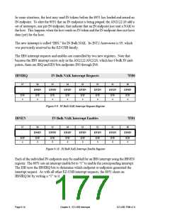
9.13 In Bulk NAK Interrupt - (AN2122/AN2126 only)
The EZ-USB family responds to an IN token from the host by loading an IN endpoint
buffer and then arming the endpoint by loading a byte count for the endpoint. After the
host successfully receives the IN data, the 8051 receives an EP-IN interrupt, signifying
that the IN endpoint buffer is once again ready to accept data.
EZ-USB TRM v1.9
Chapter 9. EZ-USB Interrupts
Page 9-13

 CYPRESS [ CYPRESS ]