CBC915 EnerChip Energy Processor
Holding the STATUS SW/ pin again for approximately ten seconds will toggle the load back to being connected
to the energy harvester. The status indicators will pulse low. Any subsequent momentary push of the switch
will result in all three status indicators toggling once, provided the batteries are charged and the output is in
regulation. Holding the STATUS SW/ pin low until the CBC915 is powered up will force the CBC915 to enter the
MPPT state.
EnerChip Charge Indicator
EnerChip charge indicator (EC CHG/) pulses low in response to STATUS SW/ being pulsed low while the
EnerChip(s) is (are) being charged. EC CHG/ state is an indication that the output is connected to the energy
harvester and the output voltage is not in regulation. It is possible – under direct sunlight conditions or other high
power transducers for instance – for the system to be in regulation yet have EnerChips not fully charged. This
indicator will be the most accurate when used indoors under normal/lower lighting conditions or with a low power
transducer. This state can take from minutes to hours to complete depending on light intensity and/or energy
available. In this state the output is disconnected from the energy harvester.
Capacitor Charge Indicator
Capacitor charge indicator (CAP CHG/). This pin pulses low in response to STATUS SW/ being pulsed low while
the output capacitor is being charged. The CAP CHG/ state occurs only on initialization, during the time the
output capacitors are being charged. This state can take minutes to hours to complete depending on the energy
available at the harvesting transducer input. In this state, the EN VOUT/ output pin is driven high.
MPPT Indicator
Maximum Peak Power Tracking indicator. This pin goes low in response to STATUS SW/ being pulsed low when
the Energy Processor is tracking the maximum peak power operating point. Engaging the MPPT state typically
takes about a minute and occurs only when the system is first initialized or when the system can no longer stay
in regulation and the input voltage has changed from the last time MPPT was completed. For example, if a light
source has changed position throughout the day and the load current remains low, no MPPT will occur. If the load
were to increase and light intensity increased or decreased, MPPT state will be entered to allow peak power to
flow to the load. Note: Anytime the MPPT state is entered, the load, if connected, will be deriving its power from
the EnerChips and not the photovoltaic cells.
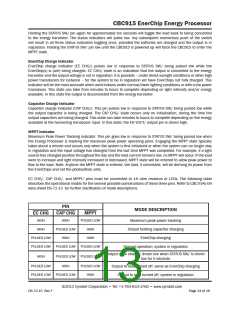
EC CHG/, CAP CHG/, and MPPT/ pins must be connected to 1K ohm resistors or LEDs. The following table
describes the operational modes for the several possible combinations of these three pins. Refer to CBC-EVAL-09
data sheet DS-72-13 for further clarification of mode descriptions.
PIN
CAP CHG
MODE DESCRIPTION
EC CHG
MPPT
HIGH
HIGH
PULSED LOW
Maximum peak power tracking
Output holding capacitor charging
EnerChip charging
HIGH
PULSED LOW
HIGH
HIGH
HIGH
PULSED LOW
PULSED LOW PULSED LOW PULSED LOW
Normal operation; system in regulation
Output state change; driven low when STATUS SW/ is driven
low for 5 seconds
HIGH
PULSED LOW PULSED LOW
PULSED LOW
HIGH
PULSED LOW
HIGH
Output to load turned off; same as EnerChip charging
Output to load turned off; system in regulation
PULSED LOW PULSED LOW
©2012 Cymbet Corporation • Tel: +1-763-633-1780 • www.cymbet.com
DS-72-15 Rev F
Page 13 of 16

 CYMBET [ CYMBET CORPORATION ]