CBC915 EnerChip Energy Processor
<@> <command number> <comma> <XXXXXYYZZUUU> <carriage return> <line feed> <zero>
X = ASCII numbers for POWER
Y = ASCII numbers for STATE
Z = ASCII numbers for TRANSDUCER TYPE
U = ASCII numbers for ENERCHIP percent charge
Response 8: Serial Communications Test Command
<@> <command number> <comma> <99> <carriage return> <line feed> <zero>
Response 9 (Not available on CBC915-ACA): Measure Transducer Power Available
<@> <command number> <comma> <ack> <carriage return> <line feed> <zero>
<ack>= ASCII ACK
Status Indicators
The following pins are used for the peak power tracking algorithm and must be connected for proper operation:
•
•
•
EC CHG/ (EnerChip Charge) - indicates EnerChip charging state.
CAP CHG/ (Capacitor Charge) - indicates capacitor charging state.
MPPT/ (Maximum Peak Power Tracking) - indicates Maximum Peak Power Tracking (MPPT) state.
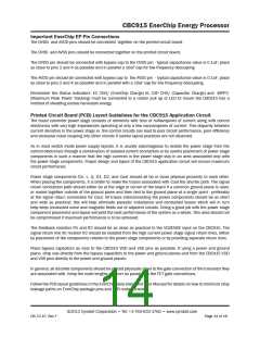
Each of these 3 pins must be either connected to a 1kΩ resistor pulled to the positive supply rail or connected
to an LED in series with a current limiting resistor pulled up to the 4.06V supply rail via a diode, as shown in
Figure 3. All three status lines must be connected to a load so the CBC915 has a way to bleed off excess energy
while in the MPPT state. Note in Figure 3 the extra diode used to isolate the large LED currents from the CBC915
bypass capacitor. This is to prevent inadvertent resetting of the CBC915. The status indicator pins are used as
a shunt regulator during peak power tracking. If these 3 pins are not connected as described, it is possible that
the CBC915 can be damaged during start-up.
There is one status input pin and three status indicators.
Status Input Pin
STATUS SW/ is pulled high internally. Tie this pin to a switch or open drain/collector output to pull low. When
pulled low STATUS SW/ will cause the EC CHG/, MPPT/, and CAP CHG/ lines to pulse low depending on the
state of the Energy Processer. When in the normal state with power applied to the system and in regulation with
fully charged EnerChips, all the lines will pulse low simultaneously. If STATUS SW/ is held low for more then 10
seconds, EN VOUT/ will go high shutting off power to the application system, subsequent pulses of less then 10
seconds will cause the EN CAP CHG/ and MPPT lines to pulse low and the EN VOUT/ line to remain in the high
or power disconnected state. Holding STATUS SW/ line low for greater then 10 seconds will restore the Energy
Processor to its normal state with EN VOUT/ in the low state with power applied to the application system and all
three status lines pulsing low in response to a low level pulse on STATUS SW/.
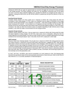
When all three status indicators simultaneously pulse low, the output is connected to the load, the EnerChips
are charged, and the system is in regulation. The status indicator corresponding to each state will automatically
pulse low when the system enters that state. The EnerChip EP operating state can be requested by pulsing
STATUS SW/ low. This will cause the corresponding indicators to pulse low.
Activating a status indicator requires a momentary (less than one second) low pulse to STATUS SW/. The
associated indicator pin will then be driven low once.
Holding the STATUS SW/ pin low for approximately ten seconds will cause the CBC915 to disconnect from the
load. If the STATUS/ pin is then momentarily pulsed low, the EC CHG/ and CAP CHG/ indicator pins will pulse low,
indicating the batteries are charged, output is in regulation, and the load is disconnected.
©2012 Cymbet Corporation • Tel: +1-763-633-1780 • www.cymbet.com
DS-72-15 Rev F
Page 12 of 16

 CYMBET [ CYMBET CORPORATION ]