CX82100 Home Network Processor Data Sheet
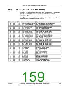
8.8.15
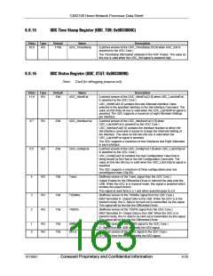
UDC Time Stamp Register (UDC_TSR: 0x0033008C)
Bit(s)
10:0
Type
RO
Default
11'b0
Name
UDC_TimeStamp
Description
(Latched version of the UDC_TimeStamp [10:0] when UDC_Sof is
asserted by the UDC Core.)
The TimeStamp information obtained in the SOF Packet. The value on
this bus is valid when the UDC_Sof signal is asserted high.
8.8.16
UDC Status Register (UDC_STAT: 0x00330090)
Note: Used for debugging purpose only.
Bit(s)
11:9
Type
RO
Default
3'b0
Name
UDC_AltIntfVal
Description
(Latched version of the UDC_AltIntfVal [2:0] when UDC_LatchIntfVal
is asserted by the UDC Core.)
UDC_AltIntfVal[1:0] contains the new Alternate Interface Value
selected in the specified Interface in the Set-Interface Command. The
value on this three bit bus is valid when the UDC_LatchIntfVal signal is
asserted. The UDC supports a maximum of eight Alternate Settings
per Interface.
8:7
6:5
4
RO
RO
RO
2'b0
2'b0
1'b0
UDC_InterfaceVal
UDC_ConfigVal
TxenL
(Latched version of the UDC_InterfaceVal [1:0] when
UDC_LatchIntfVal is asserted by the UDC Core.)
UDC_InterfaceVal[1:0] contains the Interface Number to which the
Set-Interface command is issued to change the Alternate Setting of
the Interface. The value on this two bits bus is valid when the
UDC_LatchIntfVal signal is asserted.
The UDC supports a maximum of four Interfaces and Eight Alternates
in each interface.
(Latched version of the UDC_ConfigVal [1:0] when UDC_LatchCfgVal
is asserted by the UDC Core.)
UDC_ConfigVal[1:0] contains the new Configuration Value that is
being issued by the Host in the Set-Configuration Command. The
value on this two bits bus is valid when the UDC_LatchCfgVal signal is
asserted.
The UDC supports a maximum of three configurations plus one
unconfigured state (Cfg-00).
(Buffered version of the TxenL signal from the UDC Core.)
Output Enable for the Differential Driver to transmit the data onto the
USB. When the UDC is in transmit mode, this signal is asserted which
enables the output drivers.
This signal at reset time is a 1 and when asserted goes to a 0.
(Buffered version of the TXDMns signal from the UDC Core.)
NRZI formatted D- Output Data to the USB. When the UDC is in the
transmit mode, the D- data to be sent out is transmitted via this signal.
This signal will be fed into the Differential Driver.
3
2
RO
RO
1'b0
1'b0
TXDMns
TXDPls
(Buffered version of the TXDPls signal from the UDC Core.)
NRZI formatted D+ Output Data to the USB. When the UDC is in
transmit mode, the D+ data to be sent out is transmitted via this signal.
This signal will be fed into the Differential Driver.
(Buffered version of the DMNS signal to the UDC Core.)
D- Signal from the USB to identify the SE0 signal.
(Buffered version of the DPLS signal to the UDC Core.)
D+ Signal from the USB to identify the SE0 signal.
1
0
RO
RO
1'b0
1'b0
DMNS
DPLS
101306C
Conexant Proprietary and Confidential Information
8-29

 CONEXANT [ CONEXANT SYSTEMS, INC ]