CX82100 Home Network Processor Data Sheet
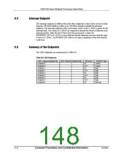
8.8.8
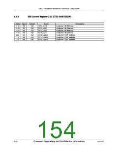
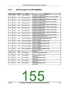
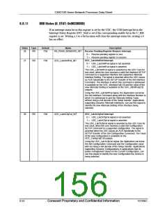
USB Control Register 1 (U_CTR1: 0x0033002C)
Bit(s)
31
Type
RW
Default
1'b0
Name
Description
USB_IE
Global USB Interrupt Enable.
0 = Disable all USB related interrupts.
1 = Enable all USB related interrupts enabled. Each individual
interrupt can be further controlled by its corresponding
interrupt enable bit.
USB Reset.
Writing a 1 will reset the entire USB device (including the UDC
Core) to default state. Software must clear this bit by writing a 0 or
reading it. This bit self-clears after being read.
Application Initiated Resume.
30
29
RW
RW
1'b1
1'b0
USB_RESET
AI_RESUME
This is an application initiated Resume signal. Writing a 1 to this bit
will resume the USB bus from the Suspended Mode. The peripheral
must assert the Dev_Resume signal to the UDC Core for one 12
MHz clock period. Setting this bit is meaningful only when the USB
bus is in the Suspended mode.
In response to this signal, the UDC will deassert the UDC_Suspend
signal, drive the non-IDLE (K State) onto the USB Cable for 12 ms,
and perform the Remote Wakeup Operation. When the
UDC_Suspend signal is deasserted in response to the assertion of
the Dev_Resume signal, the peripheral must restart the clock (to
the UDC Core) as soon as possible in order for the Core to start the
counters for counting the Wakeup sequence time.
This bit self-clears one cycle after it is been set.
Buffer Pointer Initialized Flag.
28
RW
1’b0
RV_INIT
Set by firmware before activating OUT Endpoints, but after writing
the pointer to the circular RX DMA buffer. Must be reset by firmware
at the next instruction.
Reserved. Should be written to all 0s.
Endpoint 3 IN DMA Channel Reset.
Writing a 1 to this bit resets the DMA channel associated with the
EP3_IN endpoint. Must be reset to a 0 by firmware and can be done
immediately after setting to a 1.
Endpoint 2 IN DMA Channel Reset.
Writing a 1 to this bit resets the DMA channel associated with the
EP2_IN endpoint. Must be reset to a 0 by firmware and can be done
immediately after setting to a 1.
Endpoint 1 IN DMA Channel Reset.
27:16
15
RW
RW
13'b0
1'b0
EP3_IN_DMA_RESET
EP2_IN_DMA_RESET
EP1_IN_DMA_RESET
14
13
RW
RW
1'b0
1'b0
Writing a 1 to this bit resets the DMA channel associated with the
EP1_IN endpoint. Must be reset to a 0 by firmware and can be done
immediately after setting to a 1.
8-18
Conexant Proprietary and Confidential Information
101306C

 CONEXANT [ CONEXANT SYSTEMS, INC ]