Evaluation Kit for CMX990
EV9900A
3.
Quick Start
This section provides instructions for users who wish to experiment immediately with the
evaluation kit. A more complete description of the kit and its use appears later in this document.
The EV9900A includes a CMX990 device that is described in its own, separate, datasheet.
Accordingly, the user should read the CMX990 datasheet before using the EV9900A.
3.1
Setting-Up
The following procedure is recommended:
1. Connect test leads as required, including the host µController to parallel interface J13.
2. The power amplifier output should be connected to a suitable 50Ω load.
THE USE OF AN EXTERNAL 50Ω LOAD IS ESSENTIAL TO PREVENT POSSIBLE
DAMAGE TO THE PA STAGE.
3. Power should be applied to the main supply (7.2V nominal).
4. The CMX990 device should be reset by issuing a RESET task to the host µController parallel
interface (using the TASK bits (b3 - b0) of the Command register [address $01]).
5. Power should be applied to the power amplifier supply connector (3.5V).
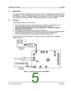
The board is now ready for operation. An example of typical connections to the EV9900A is
shown in Figure 2.
30dB RF
Attenuator
RF Spectrum
Analyzer
J6
J9
J1 J10
J8
J18
J7
+7.2V
Power Amplifier +3.5V
Ground
CMX
990
J13
J12
J11
J2
J5
J4
RF Signal
Generator
Figure 2 – Typical Connections for EV9900A
© 2007 CML Microsystems Plc
5
UM9900A/3

 CMLMICRO [ CML MICROCIRCUITS ]