RF Quadrature Transceiver / RF Quadrature Receiver
CMX991/CMX992
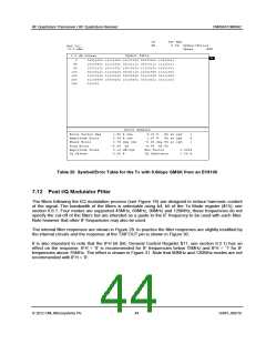
CF
SR
460 MHz
9.6k zSymbol/Errors
Ref Lvl
-9.2 dBm
Demod
MSK
Symbol Table
0.8 dB Offset
A
0
40
80
120
160
200
240
01011000 11101000 01111100 00000001 11010101
10110001 11110011 00111111 00110111 11110111
10111111 10111011 10010101 11110101 10101011
00100111 11110010 00101110 10101000 11011001
11010100 11100100 00000000 01111000 01011000
01100000 10000101 10100001 01010011 01011010
010001
Error Summary
Error Vector Mag
Magnitude Error
Phase Error
1.52
0.64
0.79 deg rms
-4.68 Hz
%
%
rms
rms
4.18
1.37
%
%
Pk at sym
Pk at sym
1
6
1
-2.34 deg Pk at sym
-4.68 Hz Pk
Freq Error
Amplitude Droop
IQ Offset
0.13 dB/sym
Rho Factor
IQ Imbalance
0.9984
0.06 %
3.69
%
Table 20 Symbol/Error Table for the Tx with 9.6kbps GMSK from an EV9100
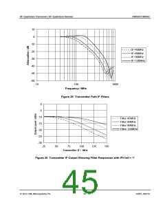
7.12 Post I/Q Modulator Filter
The filters following the I/Q modulation process (see Figure 16) are designed to reduce harmonic content
of the signal. The bandwidth of the filters is selectable using b4, b5 of the Tx Mode register ($15), see
section 6.6.1. Four modes are supported 45MHz, 60MHz, 90MHz and 120MHz; these frequencies do not
specify the cut-off of the filters but are intended as a guide to the IF frequency to be used with each filter.
Note however that other IF frequencies may also be used.
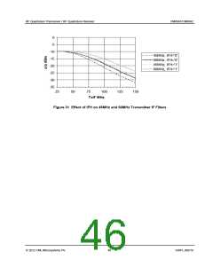
The internal filter responses are shown in Figure 29. In practice the filter responses are slightly modified by
the internal circuits and the response at the TXIFOUT pin is shown in Figure 30.
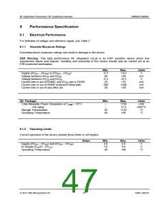
It is also important to note that the IFH bit (b6, General Control Register $11, see section 6.2.1) has an
effect on the response. IFH = ‘0’ is recommended for IF frequencies below 75MHz and IFH = ‘1’ for IF
frequencies above 75MHz. The effect is shown in Figure 31. Note that 90MHz and 120MHz modes are not
recommended with IFH = ‘0’.
2012 CML Microsystems Plc
44
D/991_992/18

 CMLMICRO [ CML MICROCIRCUITS ]