GMSK Packet Data Modem and RF Transceiver
CMX990
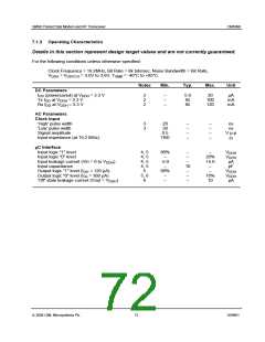
Notes
Min.
Typ.
Max.
Unit
Auxiliary ADC
Resolution
Input range
Auxiliary DAC
Resolution
Output range
–
TBD
10
–
–
TBD
bits
V
14
15
–
TBD
10
–
–
TBD
bits
V
Phase Locked Loop
Reference Input
Frequency
Level
Divide ratios
TBD
0.5
1
19.2
–
–
TBD
–
8192
MHz
Vp-p
10
11
Main RF Synthesizer
Comparison frequency
Input frequency range
Input level
–
600
-10
48000
–
–
–
–
–
±2.5
152
500
2000
-20
1048576
–
kHz
MHz
dBm
Divide ratios
Charge pump current
Normalised SSB phase noise
Aux IF Synthesizer
Comparison frequency
Input frequency range
Input level
Divide ratios
Charge pump current
Normalised SSB phase noise
mA
dBc/Hz
–
–
–
150
-10
250
–
100
–
–
–
±2.5
TBD
600
250
-20
16384
–
kHz
MHz
dBm
mA
dBc/Hz
–
–
Notes:
2. Not including any current drawn from the device pins by external circuitry.
3. Timing for the external input to the CLOCK pin.
4. WRN, RDN, CSN, A0 - A5 pins.
5. D0 - D7 pins.
6. IRQN pin.
7. Gain shown is for a matched 50W source, however the input is high impedance and a
transformer or equivalent voltage step-up circuits can be used to achieve a higher gain
figure. If such arrangements are used input third order intercept point will be degraded.
8. A divide by 2 is provided within the IC.
9. Normal input level is the range over which phase error performance is specified. The
total limiting range is an extended range, the lower end of which is intended to allow the
Tx loop to “lock up” during power up.
10. Sine wave or clipped sine wave.
11. Separate dividers provided for RF and IF PLL’s
12. TX LO chain has selectable divide by 2 or divide by 4.
13. IC contains divide by 4.
14. Aux ADC 2 and 3 have uncommitted op-amps on the input.
15. Aux DAC 0 provides a power ramp for the PA passed on a user-programmable ramp
table. Aux DAC 1 should be connected to VCXO (or VCTCXO) for AFC control.
ã 2004 CML Microsystems Plc
74
D/990/1

 CMLMICRO [ CML MICROCIRCUITS ]