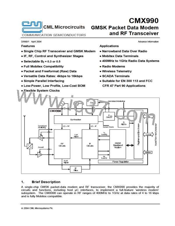
GMSK Packet Data Modem and RF Transceiver
CMX990
Notes
Min.
Typ.
Max.
Unit
AC Parameters
Rx 1st Mixer
Input frequency range
Local oscillator frequency range
IF output frequency
Gain
Input third order intercept point
Image rejection
Input impedance
Output load
Output noise voltage
400
700
44
–
TBD
TBD
–
–
–
45
0.5
+13
30
TBD
600
4.9
950
2000
46
–
–
–
–
–
–
MHz
MHz
MHz
dB
dBm
dB
W
W
nV/ÖHz
8
7
–
–
Rx IF Stages
Input frequency range
Input third order intercept (Max Gain)
Input impedance
44
–
–
45
TBD
650
8
46
–
–
MHz
dBm
W
Noise figure
–
–
dB
Maximum gain (Max AGC)
Minimum gain (Min AGC)
AGC step size
–
–
–
63
18
15
–
–
–
dB
dB
dB
AGC step size accuracy
Selectivity at ±1 to 10 MHz
Selectivity at ±1.92 MHz (ADC Alias)
I/Q image rejection
Local oscillator range
RSSI output
–
–
–
–
–
dB
dB
dB
dB
±1.5
–
–
30
180
Digital
10
55
TBD
176
13
8
184
MHz
Tx Offset Mixer
Input frequency range
Local oscillator frequency range
IF output frequency
Input level
400
700
40
TBD
–
–
–
–
–
TBD
950
2000
90
TBD
–
MHz
MHz
MHz
dBm
dB
Conversion gain
Tx Limiter/Modulator/Phase Detector
Input frequency range
Combined rms phase error
Combined peak phase error
Charge pump output current
Normal input level
40
–
–
–
-35
-91
–
3.8
14
±1.0
–
90
–
–
–
-10
-10
MHz
deg
deg
mA
dBm
dBm
W
9
9
Total limiting range
Input Impedance
–
high
IF input frequency
12
160
–
180
MHz
ã 2004 CML Microsystems Plc
73
D/990/1

 CMLMICRO [ CML MICROCIRCUITS ]