GMSK Packet Data Modem and RF Transceiver
CMX990
5.
General Description
The CMX990 comprises a baseband modem and an associated RF section to provide the air-interface to
the required Mobitex standard. Device control and status is transferred via a set of memory mapped
registers. The following paragraphs provide a description of operation of each of the sections that make
up the device.
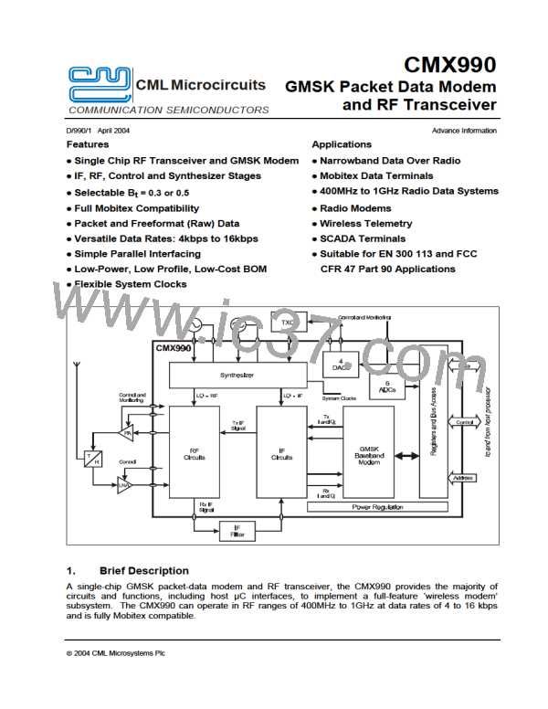
The CMX990 is composed of 5 main sections:
5.1
5.2
5.3
5.4
5.5
Baseband modem
µC interface
Auxiliary ADC and DAC
Synthesiser
RF and IF
Each of the above will be described in its own section below:
5.1
Baseband Modem
This section has been designed to be compliant with the appropriate sections of the "Mobitex
Interface Specification" including Short Block Frame formatting for the extended battery saving
protocol. References to ‘data blocks’ in this section apply to both the normal (18 byte) Data
Block and the smaller (4 byte) Short Data Block.
The function of this section is further divided into Receive and Transmit sections that operate
in half duplex.
In transmit mode the data is encoded according to the Mobitex standard. This includes the
calculation and appending of a Cyclic Redundancy Checksum (CRC) and Forward Error
Correction (FEC), and Interleaving to reduce the effects of noise. The subsequent NRZ data
stream is then filtered digitally and the resulting digital data processed to produce an I and Q
signal as the baseband form of the required FM signal. These are converted to analogue
signals via D-A converters and passed to the RF section for subsequent transmission.
In receive mode, the analogue I and Q representations, at baseband, of the FM signal from the
RF section are converted to digital signals via A-D converters. These signals are digitally
filtered to suppress the adjacent channels and demodulated digitally. The resulting signal is
then filtered, to optimise the signal to noise performance, before slicing to resolve into a digital
bit stream. Mobitex specified error correction and de-interleaving is applied and the resulting
data is presented for transfer to an external processor.
5.1.1
Description of Blocks
Status and Data Quality Registers
8-bit registers which the µC can read to determine the status of the modem and the received
data quality.
Command, Mode and Control Registers
The values written by the µC to these 8-bit registers control the operation of the modem.
Data Buffer
An 18-byte buffer used to hold receive or transmit data to or from the µC.
ã 2004 CML Microsystems Plc
15
D/990/1

 CMLMICRO [ CML MICROCIRCUITS ]