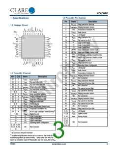
CPC75282
1.7.3 Ringing Switch, SW4
Parameter
Test Conditions
(differential) = R to R
RINGING
Symbol
Minimum
Typical
Maximum
Unit
V
SW4
LINE
All-Off state.
+25°C
V
(differential) = -255V to +210V
-
-
-
SW
V
(differential) = +255V to -210V
SW
Off-State
Leakage Current
+85° C
V
(differential) = -270V to +210V
I
-
1
μA
SW
SW
V
(differential) = +270V to -210V
SW
-40° C
V
(differential) = -245V to +210V
SW
V
(differential) = +245V to -210V
SW
I
(on) = 70mA, 80mA
(on) = 1mA
R
On Resistance
On Voltage
-
-
15
3
Ω
10
-
SW
ON
I
V
V
SW
ON
On-State
Leakage Current
Inputs set for ringing -Measure ringing
generator current to ground.
I
-
-
2
-
-
mA
mA
RINGING
1
I
Inputs set for ringing mode.
150
Steady-State Current
SW
Ringing switches on, all other switches
off. Apply 1kV 10x1000 μs pulse with
appropriate protection in place.
1
I
-
-
-
2
A
Surge Current
SW
I
Release Current
SW4 transition from on to off.
300
-
1000
μA
RINGING
+25°C, OFF = 0,
x
V (R , R ) = 320V
SW RINGING LINE
+85°C, OFF = 0,
Logic input to switch
output isolation
x
I
-
-
1
-
μA
SW
V (R , R ) = 330V
SW RINGING LINE
-40°C, OFF = 0,
x
-
V (R , R ) = 310V
SW RINGING LINE
2
-
dV/dt
1500
2100
V/μs
Transient Immunity
1
This parameter is not tested in production. Choice of secondary protector should ensure this rating is not exceeded.
2
Applied voltage is 100V square wave at 100Hz.
P-P
R00D
www.clare.com
7

 CLARE [ CLARE ]