EP9312
Universal Platform SOC Processor
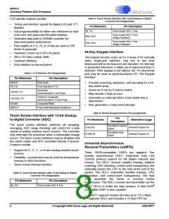
Table G. Touch Screen Interface with 12-bit Analog-to-Digital
Converter Pin Assignments
LCD-specific features include:
•
•
•
•
Timing and interface signals for digital LCD and TFT
displays
Pin Mnemonic
Pin Description
Yp, Ym
Touch screen ADC Y Axis
Full programmability for either non-interlaced or dual-
scan color and grayscale flat panel displays
Touch screen ADC X Axis
Voltage Feedback
SXp, SXm
SYp, SYm
Dedicated data path to SDRAM controller for
improved system performance
Touch screen ADC Y Axis
Voltage Feedback
Pixel depths of 4, 8, 16, or 24 bits per pixel or 256
levels of grayscale
64-Key Keypad Interface
•
•
•
•
Hardware Cursor up to 64 x 64 pixels
256 x 18 Color Lookup Table
Hardware Blinking
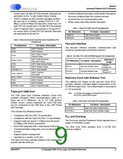
The keypad circuitry scans an 8 x 8 array of 64 normally
open, single-pole switches. Any one or two keys
depressed will be de-bounced and decoded. An interrupt
is generated whenever a stable set of depressed keys is
detected. If the keypad is not utilized, the 16 column/row
pins may be used as general purpose I/O. The Keypad
interface:
8-bit interface to low-end panel
Table F. LCD Interface Pin Assignments
Pin Mnemonic
Pin Description
SPCLK
Pixel Clock
•
Provides scanning, debounce, and decoding for a 64-
key switch array.
P[17:0]
Pixel Data Bus [17:0]
•
•
•
Scans an 8-row by 8-column matrix.
May decode 2 keys at once.
Horizontal
Synchronization / Line Pulse
HSYNC / LP
Vertical or Composite
Synchronization / Frame Pulse
Generates an interrupt when a new stable key is
determined.
VCSYNC / FP
BLANK
Composite Blank
•
Also generates a 3-key reset interrupt.
BRIGHT
Pulse Width Modulated Brightness
Table H. 64-Key Keypad Interface Pin Assignments
Pin
Touch Screen Interface with 12-bit Analog-
to-digital Converter (ADC)
Pin Mnemonic
Alternative Usage
Description
The touch screen interface performs all sampling,
averaging, ADC range checking, and control for a wide
variety of analog resistive touch screens. This controller
only interrupts the processor when a meaningful change
occurs. The touch screen hardware may be disabled and
the switch matrix and ADC controlled directly if desired.
Features include:
Key Matrix Column
Inputs
COL[7:0]
ROW[7:0]
General Purpose I/O
General Purpose I/O
Key Matrix Row
Inputs
Universal Asynchronous
Receiver/Transmitters (UARTs)
•
•
•
Support for 4-, 5-, 7-, or 8-wire analog resistive touch
screens.
Three 16550-compatible UARTs are supplied. Two
provide asynchronous HDLC (High-level Data Link
Control) protocol support for full duplex transmit and
receive. The HDLC receiver handles framing, address
matching, CRC checking, control-octet transparency, and
optionally passes the CRC to the host at the end of the
packet. The HDLC transmitter handles framing, CRC
generation, and control-octet transparency. The host
must assemble the frame in memory before
transmission. The HDLC receiver and transmitter use the
Flexibility - unused lines may be used for temperature
sensing or other functions.
Touch screen interrupt function.
Table G. Touch Screen Interface with 12-bit Analog-to-Digital
Converter Pin Assignments
Pin Mnemonic
Pin Description
Xp, Xm
Touch screen ADC X Axis
®
UART FIFOs to buffer the data streams. A third IrDA
compatible UART is also supplied.
•
UART1 supports modem bit rates up to 115.2 Kbps,
supports HDLC and includes a 16 byte FIFO for
8
©Copyright 2005 Cirrus Logic (All Rights Reserved)
DS515PP7

 CIRRUS [ CIRRUS LOGIC ]