CS49300 Family DSP
whichever communication mode is chosen by page size, and the number of discrete pages
the host.
required. The examples also include several figures
which present the different ROM configurations as
composite memory images.
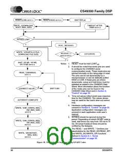
2) The host should then send the message
SOFT_RESET (0x000001). This will reset the
previously downloaded application with all of The CS49292, CS493102, and CS493112 all have
the hardware configurations in their default
states. The application code user’s guide for
special memory requirements since they must have
access to external SRAM (70nS or faster) during
each application lists those parameters which the decoding of AAC Multichannel (5.1 Channel)
are affected by a SOFT_RESET.
audio. More specifically this SRAM requirement is
ONLY required for AAC application code which is
capable of outputting 5.1 discrete channels, but is
not required of application code that offers a 2
channel downmixed output.
3) After waiting 5 ms to allow the downloaded
application to initialize, the host can send
configuration messages for both hardware and
software configuration.
Also, for the CS49330, there are certain releases
THX Surround EX (5.1 Channel and 7.1 Channel
versions), and THX Ultra2 Cinema (7.1 Channel
version only) application codes that offer
additional all-channel delay, and for this a 1Mbit or
2Mbit, 70nS SRAM is also required. The THX
Surround EX application codes (5.1 Channel or 7.1
Channel) nor the THX Ultra2 Cinema code do not
This method of resetting the DSP is usually
referred to as a “soft reset” even though it involves
toggling the reset pin.
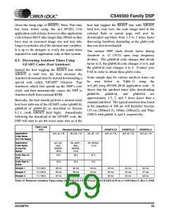
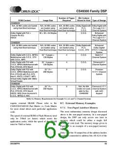
Table 12 lists some possible external memory
configurations for each DSP, in conjunction with
IBA codes stored in the host microcontroller. The
table provides a list of the ROM content, the size of
the combined memory images, the recommended
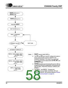
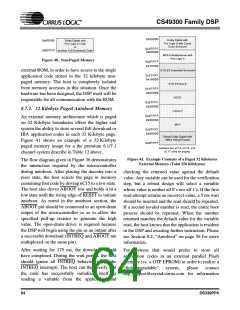
RESET(LOW) (NOTE 1)
Notes: 1. RESET must be held LOW for trstl
.
2. It should be noted that mode pins are used to configure
the CS493XX communication mode. These mode pins
are latched internally on the rising edge of reset and
can be set dynamically by a microprocessor or can be
statically pulled HIGH or LOW. If these pins are driven
dynamically, setup and hold times must be satisfied as
stated in the CS493XX Datasheet. More information
about the function of the mode pins can be found in the
CS493XX Datasheet and in Section 6, “Control” on
page 32.
RESET(HIGH) (NOTE 2)
WAIT 500 µs
WRITE_* (SOFTRESET,
MSG_SIZE)
3. 5 ms is typical but this time is application code specific
and may be as high as 10 ms. Wait times should be
verified by the designer.
4. Configuration messages determine both hardware and
software configuration. Hardware configurations are
described in Section 11 of this manual. Software
application configuration messages are described in
the Application Code User’s Guide for the code being
used.
WAIT 5 ms (NOTE 3)
WRITE_*
(CONFIGURATION_MESSAGES,
CONFIG_MSG_SIZE)
(NOTE 4)
Figure 39. Performing a Reset
62
DS339PP4

 CIRRUS [ CIRRUS LOGIC ]