CS49300 Family DSP
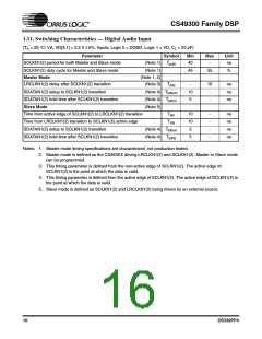
1.14. Switching Characteristics — Digital Audio Output
(TA = 25 °C; VA, VD[3:1] = 2.5 V 5%; Inputs: Logic 0 = DGND, Logic 1 = VD, CL = 20 pF)
Parameter
Symbol
Min
Max
Unit
MCLK period
(Note 1)
Tmclk
40
-
ns
MCLK duty cycle
(Note 1)
(Note 2)
40
40
60
-
%
SCLK period for Master or Slave mode
Tsclk
ns
SCLK duty cycle for Master or Slave mode
(Note 2)
45
55
%
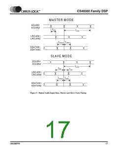
Master Mode
(Note 2, 3)
SCLK delay from MCLK rising edge, MCLK as an input
SCLK delay from MCLK rising edge, MCLK as an output
Tsdmi
Tsdmo
Tlrds
15
10
10
10
ns
ns
ns
ns
–5
LRCLK delay from SCLK transition
AUDATA2–0 delay from SCLK transition
Slave Mode
(Note 4)
(Note 4)
(Note 5)
Tadsm
Time from active edge of SCLKN1(2) to LRCLKN1(2) transition
Time from LRCLKN1(2) transition to SCLKN1(2) active edge
Tstlr
Tlrts
10
10
-
-
ns
ns
ns
AUDATA2–0 delay from SCLK transition
(Note 4, 6)
Tadss
15
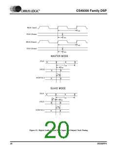
Notes: 1. MCLK can be an input or an output. These specifications apply for both cases.
2. Master mode timing specifications are characterized, not production tested.
3. Master mode is defined as the CS493XX driving both SCLK and LRCLK. When MCLK is an input, it is
divided to produce SCLK and LRCLK.
4. This timing parameter is defined from the non-active edge of SCLK. The active edge of SCLK is the
point at which the data is valid.
5. Slave mode is defined as SCLK and LRCLK being driven by an external source.
6. This specification is characterized, not production tested.
DS339PP4
19

 CIRRUS [ CIRRUS LOGIC ]