CS4365
DIF2
DIF1
DIFO
DESCRIPTION
1
1
1
1
0
0
1
1
0
1
0
1
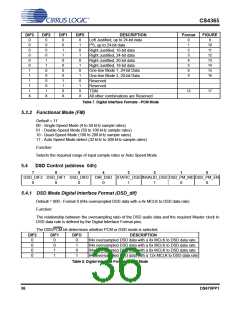
128x oversampled DSD data with a 2x MCLK to DSD data rate
128x oversampled DSD data with a 3x MCLK to DSD data rate
128x oversampled DSD data with a 4x MCLK to DSD data rate
128x oversampled DSD data with a 6x MCLK to DSD data rate
Table 8. Digital Interface Formats - DSD Mode
5.4.2 Direct DSD Conversion (DIR_DSD)
Function:
When set to 0 (default), DSD input data is sent to the DSD processor for filtering and volume control func-
tions.
When set to 1, DSD input data is sent directly to the switched capacitor DACs for a pure DSD conversion.
In this mode the full scale DSD and PCM levels will not be matched (see Section 2), the dynamic range
performance may be reduced, the volume control is inactive, and the 50 kHz low pass filter is not available
(see section 2 for filter specifications).
5.4.3 Static DSD Detect (static_DSD)
Function:
When set to 1 (default), the DSD processor checks for 28 consecutive zeroes or ones and, if detected,
sends a mute signal to the DACs. The MUTEC pins will eventually go active according to the DAMUTE reg-
ister.
When set to 0, this function is disabled.
5.4.4 Invalid DSD Detect (invalid_DSD)
Function:
When set to 1, the DSD processor checks for greater than 24 out of 28 bits of the same value and, if de-
tected, will attenuate the data sent to the DACs. The MUTEC pins go active according to the DAMUTE
register.
When set to 0 (default), this function is disabled.
5.4.5 DSD Phase Modulation Mode Select (DSD_PM_mode)
Function:
When set to 0 (default), the 128Fs (BCKA) clock should be input to DSD_SCLK for phase modulation mode.
(See Figure 20 on page 27)
When set to 1, the 64Fs (BCKD) clock should be input to DSD_SCLK for phase modulation mode.
5.4.6 DSD Phase Modulation Mode Enable (DSD_pm_EN)
Function:
When set to 1, DSD phase modulation input mode is enabled and the DSD_PM_MODE bit should be set
accordingly.
When set to 0 (default), this function is disabled (DSD normal mode).
DS670PP1
37

 CIRRUS [ CIRRUS LOGIC ]