CM6805BO
10-PIN Green-Mode PFC/PWM Combo CONTROLLER
APPLICATIONS
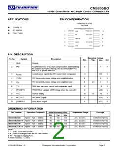
PIN CONFIGURATION
10 Pin SSOP (R10)
Top View
Desktop PC
AC Adaptor
Open Frame
PIN DESCRIPTION
Operating Voltage
Description
Pin No.
Symbol
Min.
Typ.
Max.
Unit
1
2
GND
IAC
Ground
Feedforward input to do slope compensation and to start up
the system. During the start up, IAC is connected to VCC
until VCC is greater than 13V.
0
7
V
3
Current sense input to the PFC current limit comparator
-5
0.7
V
ISENSE
VEAO
4
5
PFC transconductance voltage error amplifier output
PFC transconductance voltage error amplifier input
0
0
6
3
V
V
2.5
15
VFB
6
7
V + I
PWM feed back and current limit comparator input
PFCOFFB; it can turn off PFC stage when it is below 5V.
Positive supply
0
0
1.5
VCC
18
V
V
V
V
V
PFCOFFB
VCC
8
10
0
9
PFC OUT
PWM OUT
PFC driver output
VCC
VCC
10
PWM driver output
0
ORDERING INFORMATION
Part Number
Operation Frequency
Initial Accuracy (KHz)
Temperature Range
Package
Min
90
Typ
100
100
100
100
Max
110
110
110
110
CM6805BOGIR
Fpwm = Fpfc = 100Khz
10 Pin SSOP(R10)
10 Pin SSOP(R10)
10 Pin SSOP(R10)
10 Pin SSOP(R10)
-40℃ to 125℃
-40℃ to 125℃
-40℃ to 125℃
-40℃ to 125℃
CM6805BOGIRTR* Fpwm = Fpfc = 100Khz
CM6805BOXIR*
Fpwm = Fpfc = 100Khz
90
90
CM6805BOXIRTR* Fpwm = Fpfc = 100Khz
90
Note:
1. G : Suffix for Pb Free Product
2. X : Suffix for Halogen Free and PB Free Product
3. TR : Package is Typing Reel
4. Initial Accuracy : TA=25℃
2010/04/20 Rev 1.3
Champion Microelectronic Corporation
Page 2

 CHAMP [ CHAMPION MICROELECTRONIC CORP. ]