CM6805BO
10-PIN Green-Mode PFC/PWM Combo CONTROLLER
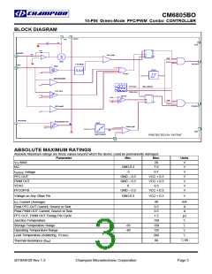
Functional Description
Detailed Pin Descriptions
IAC (Pin 2)
Typically, it has
The CM6805BO consists of an ICST (Input Current
Shaping Technique), CCM (Continuous Conduction Mode)
or DCM (Discontinuous Conduction Mode) boost PFC
(Power Factor Correction) front end and a synchronized
PWM (Pulse Width Modulator) back end. The CM6805BO
is designed to replace FAN4803 (8 pin SOP package),
which is the second generation of the ML4803 with 8 pin
package. It is distinguished from earlier combo controllers
by its low count, innovative input current shaping technique,
and very low start-up and operating currents. The PWM
section is dedicated to peak current mode operation. It uses
conventional trailing-edge modulation, while the PFC uses
a
feed-forward resistor, RAC,
4Mega~10Mega ohm resistor connected between this pin
and rectified line input voltage.
The current of RAC will program the automatic slope
compensation for the system. This feed-forward signal can
increase the signal to noise ratio for the light load condition
or the high input line voltage condition.
ISENSE (Pin 3)
This pin ties to a resistor which senses the PFC input
current. This signal should be negative with respect to the IC
ground. It internally feeds the pulse-by-pulse current limit
comparator and the current sense feedback signal. The
ILIMIT trip level is –1V. The ISENSE feedback is internally
multiplied by a gain of four and compared against the internal
programmed ramp to set the PFC duty cycle. The
intersection of the boost inductor current down-slope with the
internal programming ramp determines the boost off-time.
leading-edge
modulation.
This
patented
Leading
Edge/Trailing Edge (LETE) modulation technique helps to
minimize ripple current in the PFC DC bus capacitor.
The main improvements from ML4803 are:
1.
2.
Add Green Mode Functions for both PFC and PWM
Remove the one pin error amplifier and add back the
slew rate enhancement GMv, which is using voltage
input instead of current input. This transconductance
amplifier will increase the transient response 5 to 10
times from the conventional OP
It requires a RC filter between ISENSE and PFC boost
sensing resistor.
3.
4.
VFB PFC OVP comparator
PFC Tri-Fault Detect for UL1950 compliance and
enhanced safety
VEAO (Pin 4)
This is the PFC slew rate enhanced transconductance
amplifier output which needs to connected with
compensation network Ground.
a
5.
A feed forward signal from IAC pin is added to do the
automatic slope compensation. This increases the
signal to noise ratio during the light load; therefore,
THD is improved at light load and high input line
voltage.
CM6805BO does not require the bleed resistor and it
uses the more than 800k ohm resistor between IAC
pin and rectified line voltage to feed the initial current
before the chip wakes up.
VIN-OK comparator is added to guaranteed PWM
cannot turn on until VFB reaches 2.5V in which PFC
boost output is about steady state, typical 380V.
A 10mS digital PWM soft start circuit is added
10 pin SOP package
VFB (Pin 5)
Besides this is the PFC slew rate enhanced
transconductance input, it also tie to a couple of protection
comparators, PFCOVP, and PFC Tri-Fault Detect
6.
7.
V + I (Pin 6)
This pin is tied to the primary side PWM current sense
resistor or transformer. It provides the internal pulse-by-pulse
current limit for the PWM stage (which occurs at 1.5V) and
the peak current mode feedback path for the current mode
control of the PWM stage. Besides current information, the
photo-couple also goes into V + I pin. Therefore, it is the
SUM Amplifier input.
8.
9.
10. No internal Zener and VCCOVP comparator
The CM6805BO operates both PFC and PWM sections at
100kHz. This allows the use of smaller PWM magnetic and
output filter components, while minimizing switching losses
in the PFC stage.
Soft Start is around 10mS after the startup(VCC is greater
than 13V).
Several protection features have been built into the
CM6805BO. These include soft-start, redundant PFC
overvoltage protection, PFC Tri-Fault Detect, VIN-OK, peak
current limiting, duty cycle limiting, under-voltage lockout,
reference ok comparator PFCOFFB.
2010/04/20 Rev 1.3
Champion Microelectronic Corporation
Page 7

 CHAMP [ CHAMPION MICROELECTRONIC CORP. ]