CM6802
NO BLEED RESISTOR GREEN MODE PFC/PWM CONTROLLER COMBO
APPLICATIONS
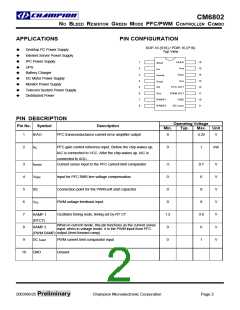
PIN CONFIGURATION
SOP-16 (S16) / PDIP-16 (P16)
ꢀ
ꢀ
ꢀ
ꢀ
ꢀ
ꢀ
ꢀ
ꢀ
ꢀ
Desktop PC Power Supply
Top View
Internet Server Power Supply
IPC Power Supply
1
2
3
4
5
6
7
8
VEAO
16
15
14
13
12
11
10
9
IEAO
IAC
UPS
Battery Charger
DC Motor Power Supply
Monitor Power Supply
Telecom System Power Supply
Distributed Power
VFB
VREF
ISENSE
VCC
VRMS
SS
PFC OUT
VDC
PWM OUT
GND
RAMP1
RAMP2
DC ILIMIT
PIN DESCRIPTION
Operating Voltage
Pin No.
Symbol
Description
Min.
Typ.
Max.
Unit
1
IEAO
PFC transconductance current error amplifier output
0
4.25
V
2
IAC
PFC gain control reference input. Before the chip wakes up,
IAC is connected to VCC. After the chip wakes up, IAC is
0
1
mA
3
4
ISENSE
VRMS
SS
Current sense input to the PFC current limit comparator
-5
0
0.7
6
V
V
V
V
V
V
V
Input for PFC RMS line voltage compensation
Connection point for the PWM soft start capacitor
PWM voltage feedback input
5
0
8
6
0
8
VDC
7
Oscillator timing node; timing set by RT CT
1.2
0
3.9
6
RAMP 1
(RTCT)
When in current mode, this pin functions as the current sense
input; when in voltage mode, it is the PWM input from PFC
output (feed forward ramp).
8
RAMP 2
(PWM RAMP)
9
DC ILIMIT
GND
PWM current limit comparator input
0
1
10
Ground
2003/06/25 Preliminary
Champion Microelectronic Corporation
Page 2

 CHAMP [ CHAMPION MICROELECTRONIC CORP. ]