CAT5112
AC CONDITIONS OF TEST
Range
V
2.5V ≤ V
≤ 6V
CC
CC
Input Pulse Levels
0.2V to 0.7V
CC CC
Input Rise and Fall Times
Input Reference Levels
10ns
0.5V
CC
AC OPERATING CHARACTERISTICS:
VCC = +2.5V to +6.0V, VH = VCC, VL = 0V, unless otherwise specified
Symbol Parameter
Min
Typ(1)
Max
Units
tCI
CS to INC Setup
100
50
100
250
250
1
—
—
—
—
—
—
—
—
1
—
—
—
—
—
—
—
—
5
ns
ns
tDI
U/D to INC Setup
tID
U/D to INC Hold
ns
tIL
INC LOW Period
ns
tIH
INC HIGH Period
ns
tIC
INC Inactive to CS Inactive
CS Deselect Time (NO STORE)
CS Deselect Time (STORE)
INC to VOUT Change
INC Cycle Time
µs
tCPH
tCPH
tIW
100
10
—
ns
ms
µs
tCYC
1
—
—
—
5
—
500
1
µs
(2)
tR, tF
INC Input Rise and Fall Time
Power-up to Wiper Stable
Store Cycle
—
µs
(2)
tPU
—
msec
ms
tWR
—
10
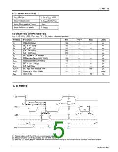
A. C. TIMING
CS
(store)
tCYC
tIC
tCPH
tCI
tIL
tIH
90%
90%
INC
10%
tID
tDI
tR
tF
U/D
(3)
tIW
MI
R
W
(1) Typical values are for T =25˚C and nominal supply voltage.
A
(2) This parameter is periodically sampled and not 100% tested.
(3) MI in the A.C. Timing diagram refers to the minimum incremental change in the W output due to a change in the wiper position.
Doc. No. 2002, Rev. L
5

 CATALYST [ CATALYST SEMICONDUCTOR ]