CAT5112
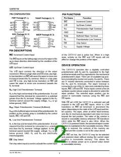
PIN CONFIGURATION
PDIP Package (P, L)
PIN FUNCTIONS
Pin Name
Function
TSSOP Package (U, Y)
INC
Increment Control
Up/Down Control
Potentiometer High Terminal
Ground
1
2
3
4
8
7
6
5
V
R
R
CS
1
2
3
4
8
7
6
5
INC
CC
L
V
CS
CC
U/D
U/D
WB
R
L
R
H
GND
INC
R
H
R
H
GND
R
U/D
WB
GND
SOIC Package (S, V)
MSOP Package (R, Z)
R
WB
R
L
Buffered Wiper Terminal
Potentiometer Low Terminal
Chip Select
1
2
3
4
8
7
6
5
V
INC
CC
1
2
3
4
8
7
6
5
INC
VCC
CS
U/D
U/D
CS
R
L
R
H
CS
R
H
R
R
L
GND
R
WB
GND
VCC
Supply Voltage
WB
PIN DESCRIPTIONS
INC: Increment Control Input
of the CAT5112 and is active low. When in a high
state, activity on the INC and U/D inputs will not
affect or change the position of the wiper.
TheINCinput(onthefallingedge)movesthewiperinthe
up or down direction determined by the condition of the
U/D input.
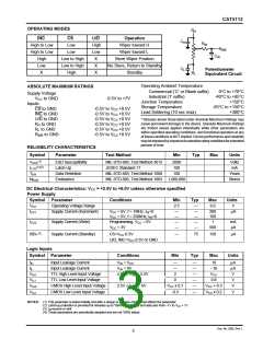
DEVICE OPERATION
U/D: Up/Down Control Input
The CAT5112 operates like a digitally controlled
potentiometer with RH and RL equivalent to the high
andlowterminalsandRWB equivalentto themechanical
potentiometer's wiper. There are 32 available tap posi-
tions including the resistor end points, RH and RL. There
are 31 resistor elements connected in series between
the RH and RL terminals. The wiper terminal is
connected to one of the 32 taps and controlled by three
inputs, INC, U/D and CS. These inputs control a five-bit
up/down counter whose output is decoded to select the
wiper position. The selected wiper position can be
stored in nonvolatile memory using the INC and
CS inputs.
The U/D input controls the direction of the wiper
movement. When in a high state and CS is low, any high-
to-low transition on INC will cause the wiper to move one
increment toward the RH terminal. When in a low state
and CS is low, any high-to-low transition on INC will
cause the wiper to move one increment towards the
RL terminal.
RH: High End Potentiometer Terminal
RH is the high end terminal of the potentiometer. It is not
required that this terminal be connected to a potential
greater than the RL terminal. Voltage applied to the RH
terminal cannot exceed the supply voltage, VCC or go
below ground, GND.
With CS set LOW the CAT5112 is selected and will
respond to the U/D and INC inputs. HIGH to LOW
transitions on INC wil increment or decrement the
wiper (depending on the state of the U/D input and five-
bit counter). The wiper, when at either fixed terminal,
acts like its mechanical equivalent and does not move
beyond the last position. The value of the counter is
stored in nonvolatile memory whenever CS transitions
HIGH while the INC input is also HIGH. When the
CAT5112ispowered-down,thelaststoredwipercounter
position is maintained in the nonvolatile memory. When
power is restored, the contents of the memory are
recalled and the counter is set to the value stored.
RWB: Wiper Potentiometer Terminal (Buffered)
RWB is the buffered wiper terminal of the potentiometer. Its
position on the resistor array is controlled by the control
inputs, INC, U/D and CS.
RL: Low End Potentiometer Terminal
RL is the low end terminal of the potentiometer. It is not
required that this terminal be connected to a potential
less than the RH terminal. Voltage applied to the RL
terminal cannot exceed the supply voltage, VCC or go
below ground, GND. RL and RH are electrically
interchangeable.
With INC set low, the CAT5112 may be de-selected
and powered down without storing the current wiper
position in nonvolatile memory. This allows the
system to always power up to a preset value stored
in nonvolatile memory.
CS: Chip Select
The chip select input is used to activate the control input
Doc. No. 2002, Rev. L
2

 CATALYST [ CATALYST SEMICONDUCTOR ]