|
16
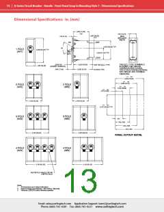
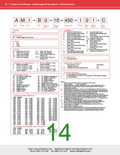
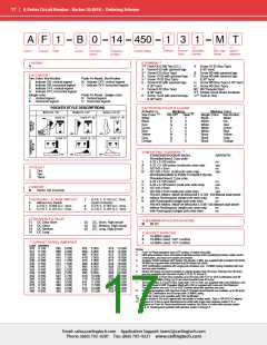
A-Series Circuit Breaker - Rocker UL Recognized – Ordering Scheme
A F 1 B 0 24 630 2 3 1 D
8
9
10
Mounting/
Barriers
11
Agency
Approval
1
2
3
4
5
6
7
Terminal
Actuator
Color
Series
Actuator
Poles
Circuit
Aux/Alarm
Switch
Frequency
& Delay
Current Rating
7 CURRENT RATING (AMPERES)
CODE AMPERES
1 SERIES
A
020 0.020
025 0.025
030 0.030
035 0.035
040 0.040
045 0.045
050 0.050
055 0.055
060 0.060
065 0.065
070 0.070
075 0.075
080 0.080
085 0.085
090 0.090
095 0.095
210 0.100
215 0.150
220 0.200
225 0.250
230 0.300
235 0.350
240 0.400
245 0.450
250 0.500
255 0.550
260 0.600
265 0.650
270 0.700
275 0.750
280 0.800
285 0.850
290 0.900
295 0.950
410 1.000
512 1.250
415 1.500
517 1.750
420 2.000
522 2.250
527 2.750
430 3.000
435 3.500
440 4.000
445 4.500
450 5.000
455 5.500
460 6.000
465 6.500
470 7.000
475 7.500
480 8.000
485 8.500
490 9.000
495 9.500
610 10.000
710 10.500
611 11.000
711 11.500
612 12.000
712 12.500
613 13.000
614 14.000
615 15.000
616 16.000
617 17.000
618 18.000
620 20.000
622 22.000
624 24.000
625 25.000
630 30.000
1
2 ACTUATOR
Two Color Visi-Rocker
C
D
F
G
H
Indicate ON, vertical legend
Indicate ON, horizontal legend
Indicate OFF, vertical legend
Indicate OFF, horizontal legend
Indicate OFF, no legend
Push-To-Reset, Visi-Rocker
N
O
P
Indicate OFF, vertical legend
Indicate OFF, horizontal legend
Indicate OFF, no legend
Single color
J
K
L
Vertical legend
Horizontal legend
No legend
8
635 35.000
8
640 40.000
Push-To-Reset , Single color
8
645 45.000
R
U
V
Vertical legend
Horizontal legend
No legend
8
650 50.000
8
OR VOLTAGE COIL (NORMAL RATED VOLTAGE)
CODE AMPERES
A06
6 DC
A32 32 DC
A48 48 DC
A65 65 DC
J12 12 AC
J18 18 AC
J24 24 AC
J48 48 AC
J65
65 AC
A12 12 DC
A18 18 DC
A24 24 DC
K20 120 AC
L40 240 AC
3 POLES
One
1
2
Two
3
Three
J06
6 AC
4
4
4,5
4 CIRCUIT
F
Relay Trip (Current)
Relay Trip (Voltage)
3
11
A
B
C
D
E
Switch Only (No Coil)
G
H
8 TERMINAL
12
13
Series Trip (Current)
Series Trip (Voltage)
Shunt Trip (Current)
Shunt Trip (Voltage)
Dual Coil with Shunt Trip
Voltage Coil
1
2
3
4
5
6
Push-On 0.250 Tab (Q.C.)
Screw 8-32 with upturned lugs
Screw 8-32 (Bus Type)
Screw 10-32 with upturned lugs
Screw 10-32 (Bus Type)
Screw 8-32 with upturned lugs
& 30° bend
E
F
Screw M4 (Bus Type)
Screw M5 with upturned lugs
& 30° bend
4
4
4,5
13
13
K
Dual Coil with Relay Trip
Voltage Coil
G
H
L
M
P
Q
R
Screw M5 (Bus Type) & 30° bend
Screw M5 (Bus Type)
0.250 Q.C./ Solder Lug
M6 Threaded Stud
13
14
13
15
16
6,7
5 AUXILIARY / ALARM SWITCH
5
7
S.P.S.T., 0.093 Q.C. Term.
(Gold Contacts)
0
1
2
4
without Aux Switch
7
8
9
Screw 8-32 (Bus Type)
& 30° bend
Printed Circuit Board Terminals
Push-In Stud
S.P.D.T., 0.093 Q.C. Term.
S.P.D.T., 0.110 Q.C. Term.
S.P.D.T., 0.093 Q.C. Term.
(Gold Contacts)
S.P.S.T., 0.110 Q.C. Term.
(Gold Contacts)
Screw 10-32 with upturned lugs
& 30° bend
Screw M4 with upturned lugs
& 30° bend
8
9
S.P.S.T., 0.187 Q.C. Term.
S.P.D.T., 0.187 Q.C. Term.
17
Screw 10-32 (Bus Type)
& 30° bend
S
T
Push-On 0.110 Tab (Q.C.)
& 30° bend
B
C
Screw M5 with upturned lugs
Screw M4 with upturned lugs
Screw M4 (Bus Type)
& 30° bend
6 FREQUENCY & DELAY
03
10
11
12
14
16
20
21
22
24
26
DC 50/60Hz, Switch Only
DC Instantaneous
DC Ultra Short
30
DC, 50/60Hz Instantaneous
DC, 50/60Hz Ultra Short
DC, 50/60Hz Short
31
32
34
36
42
44
46
52
54
56
9 ACTUATOR COLOR & LEGEND
Actuator or
Marking:
ON-OFF Dual
Marking Color
Single Color Visi-Rocker
DC Short
DC, 50/60Hz Medium
DC, 50/60Hz Long
12
12
Visi-Color
White
Black
I-O
A
C
F
DC Medium
DC Long
9
9
9
9
9
9
B
D
G
J
1
2
3
4
5
6
7
8
Black
White
White
White
White
Black
Black
Black
White
n/a
50/60Hz Short, High-inrush
50/60Hz Instantaneous
50/60Hz Ultra Short
50/60Hz Short
50/60Hz Medium, High-inrush
Red
Red
50/60Hz Long, High-inrush
Green
Blue
H
K
M
P
Green
Blue
Yellow
Gray
Orange
DC, Short, High-inrush
L
50/60Hz Medium
50/60Hz Long
DC, Medium, High-inrush
Yellow
Gray
N
Q
S
DC, Long, High-inrush
Notes:
Orange
R
1
2
Push-To-Reset actuators have OFF portion of rocker shrouded.
Multi-pole breakers have all breakers identical except when specifying Auxiliary switch and/or mixed
poles, and have one rocker per breaker.
Switch Only circuits, rated up to 50 amps & 3 poles, are available only when tied to a protected pole
(Circuit Code B, C, D or H.), For .02 to 30 amps, select Current Code 630.
For 35 - 50 amps, select Current Code 650.
Available with terminal Codes 1, 2 and 3. Current Rating limited to 30 amps maximum.
Consult factory for Dual Coil options, as special catalog number is required.
With Shunt construction, Dual Coils will trip instantaneously on line voltage. Dual coils require 30VA
minimum power to trip and are rated for intermittent duty only.
Auxiliary Switch breakers with Series Trip & Switch Only circuits: ≤ 30A, are supplied with
standard half shells. 30-50A are supplied with extended boat (B-Style) half shells.
On multi-pole breakers, one auxiliary switch is supplied, mounted in the extreme right pole.
Separate pole type voltage coils not rated for continuous duty. Available only with delay codes 10 & 20.
Available with Circuit Codes B & D only. VDE Certified to 30 amps. UL Recognized, CSA Accepted
& TUV Certified to 50 amps.
10 Series Trip current ratings: VDE Certification available with single pole breakers with DC Delay only.
UL Recognition & CSAAccepted available in one and two pole breakers.
11 Screw Terminals are recommended on ratings greater than 20 amps. Ratings over 30 amps are only
available with Terminal Codes 5, 9, G, H, M and Q.
12 Terminal Code 1: VDE Certification up to 25 amps and UL Recognition and CSAAccepted up to 30
amps, but not recommended over 20 amps.
20
3
10 MOUNTING / BARRIERS
STANDARD ROCKER BEZEL
Threaded Insert, 2 per pole
6-32 x 0.195 inches
BARRIERS
4
5
1
no
A
2
6-32 X 0.195 inches (multi-pole units only)
ISO M3 x 5mm
yes
no
6
B
ISO M3 x 5mm (multi-pole units only)
ROCKERGUARD & PUSH-TO-RESET BEZEL
Threaded Insert, 2 per pole
6-32 x 0.195 inches
yes
7
8
9
3
no
C
4
D
6-32 x 0.195 inches (multi-pole units only)
ISO M3 x 5mm
yes
no
ISO M3 x 5mm (multi-pole units only)
yes
FRONT PANEL SNAP-IN BRACKET, 0.744” [18.90mm] wide bezel
8
H
without Rockerguard (single pole units only)
with Rockerguard (single pole units only)
no
no
FRONT PANEL SNAP-IN BRACKET, 0.96” [24.48mm] wide bezel
13 Terminal Codes 3, 5 E & H (Bus Type) with VDE, are supplied with Lock Washers; Terminal Code M
(M6 Threaded Stud) with VDE is supplied with Lock and Flat Washers. These breakers are only VDE
Certified when the washers are used.
14 VDE Cert. available up to 12 amps. UL Rec. & CSAAccepted available up to 30 amps.
15 Single pole breakers with Terminal Code P (Printed Circuit Board) are available up to 30 amps with
VDE Certification and 50 amps with UL Recognition and CSAAccepted, with Circuit Codes A, B & C.
Two pole breakers with Terminal Code P (Printed Circuit Board) are available up to 40 amps with
UL Recognition and CSA Certification with Circuit Codes A, B and C.
9
J
without Rockerguard (single pole units only)
with Rockerguard (single pole units only)
no
no
11 AGENCY APPROVAL
C
D
E
I
UL Recognized & CSA Accepted
16 Terminal Code Q not available with VDE.
VDE Certified, UL Recognized & CSA Accepted
TUV Certified, UL Recognized & CSA Accepted
UL Recognized STD 1077, UL Recognized 1500 (ignition protected),
& CSA Accepted
17 Terminal Code S used on voltage coil circuit constructions only.
18 Color shown is visi and legend with remainder of rocker black.
19 Dual = ON-OFF/I-O legend with actuator. None = no legend on actuator
20 Legend on Push-to-reset bezel/shroud is white with single color actuator codes R, & U. Legend on
Push-to-reset bezel/shroud matches Visi-color of rocker with actuator codes N & O.
Rockerguard available with actuator codes C through L.
Email: sales@carlingtech.com Application Support: team2@carlingtech.com
Phone: (860) 793–9281 Fax: (860) 793–9231 www.carlingtech.com

 Carling Technologies [ Carling Technologies ]