LH0032 / LH0032C
CORPORATION
capacitance to the inverting input should be compensated by
a small capacitor across the feedback resistor. The value is
strongly dependent on layout and closed loop gain, but will
typically be in the neighborhood of several picofarads.
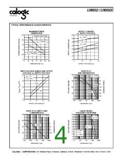
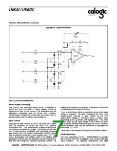
Compensation
Two compensation schemes may be used, depending on the
designer’s specific needs.
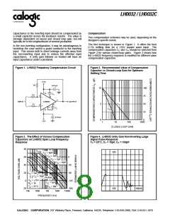
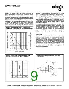
The first technique is shown in Figure 1. It offers the best
0.1% settling time for a ±10V square wave input. The
compensation capacitors CC and CA should be selected from
Figure 2 for various closed-loop gains. Figure 3 shows how
the LH0032 frequency response is modified for different value
compensation capacitors.
In the non-inverting configuration, it may be advantageous to
bootstrap the case and/or a guard conductor to the inverting
input. This serves both to divert leakage currents away from
the non-inverting input and to reduce the effective input
capacitance. A unity gain follower so treated will have an
input capacitance under a picofarad.
Figure 1. LH0032 Frequency Compensation Circuit
Figure 2. Recommended Value of Compensation
Capacitor vs Closed-Loop Gain for Optimum
Settling Time
+15V
R3
0.01µF
10
5
100
75
50
25
0
12
CA
R2
5
6
_
+
4
11
INPUT
LH0032
OUTPUT
C
R1
3
C
2
CC
C
10
A
0.01µF
0
-15V
1
10
100
1000
CLOSED LOOP GAIN
Figure 3. The Effect of Various Compensation
Capacitors on LH0032 Open Loop Frequency
Response
Figure 4. LH0032 Unity Gain Non-Inverting Large
Signal Pulse Response:
TA = 25oC, CC = 10pF, CA = 100pF
80
A
VOL
10V
C
= 0pF
C
C
= 1pF
C
60
40
20
0
0
C
= 5pF
C
C
= 10pF
C
-45
-90
-135
-180
C
= 5pF
C
C
C
= 10pF
PHASE
V
= ±15V
S
C
= 1pF
R = 1k
C
L
T = 25˚C
A
C
= 0pF
C
-20
10V
100nS
10k
100k
1M
10M
100M
FREQUENCY (Hz)
CALOGIC CORPORATION, 237 Whitney Place, Fremont, California 94539, Telephone: 510-656-2900, FAX: 510-651-1076

 CALOGIC [ CALOGIC, LLC ]