PRODUCT SPECIFICATION
TMC22091/TMC22191
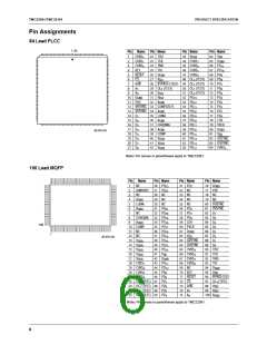
Pin Descriptions (continued)
Pin Number
84-Lead 100-Lead
Pin Name
PLCC
MQFP
Value
Pin Function Description
Chip Select. When CS is HIGH, the microprocessor interface
CS
6
72
TTL
port, D , is set to HIGH impedance and ignored. When CS is
7-0
LOW, the microprocessor can read or write parameters over
D . One additional falling edge of CS is needed to move input
7-0
data to its assigned working registers.
R/W
7
5
73
71
TTL
TTL
Bus Read/Write Control. When R/W and CS are LOW, the
microprocessor can write to the control registers or CLUT over
D . When R/W is HIGH and CS is LOW, it can read the
7-0
contents of any CLUT address or control register over D
.
7-0
RESET
Master Reset Input. Bringing RESET LOW sets the software
reset control bit, SRESET, LOW, forcing the internal state
machines to their starting states and disabling all outputs.
Bringing RESET HIGH synchronizes the internal pixel clock
(PCK = PXCK / 2) to maintain a defined pipeline delay through
the TMC22x91. If HRESET is set HIGH, the encoder is enabled
when RESET goes HIGH. If HRESET is LOW, the host restarts
the TMC22x91 by setting SRESET HIGH. RESET does not
affect the CLUT or the control registers, except SRESET.
Video Output
COMPOSITE
33
35
37
2
5
8
1 V
1 V
1 V
NTSC/PAL Video. Analog output of composite D/A converter,
nominally 1.35 volt peak-to-peak into a 37.5Ω load.
P-P
P-P
P-P
LUMA
Luminance-only Video. Analog output of luminance D/A
converter, nominally 1.35 volt peak-to-peak into a 37.5Ω load.
CHROMA
Chrominance-only Video. Analog output of chrominance D/A
converter, nominally 1.35 volt peak-to-peak into a 37.5Ω load.
Analog Interface
V
30
39
31
98
10
99
+1.23 V Voltage Reference Input. External voltage reference input,
REF
internal voltage reference output, nominally 1.235 V.
COMP
0.1 µF Compensation Capacitor. Connection point for 0.1µf
decoupling capacitor.
R
392Ω
Current-setting Resistor. Connection point for external
REF
current-setting resistor for D/A converters. The resistor (392Ω)
is connected between R
and A . Output video levels
REF
GND
are inversely proportional to the value of R
REF
.
JTAG Test Interface
TDI
25
93
92
TTL
TTL
Data Input Port. Boundary scan data input port.
TMS
24
Scan Select Input. Boundary scan (HIGH)/normal operation
(LOW) selector.
TCK
23
22
91
90
TTL
TTL
Scan Clock Input. Boundary scan clock.
TDO
Data Output Port. Boundary scan data output port.
Power Supply
V
V
27, 64, 81 41, 62, 95
40-43 13-17
+5 V
+5 V
Positive digital power supply.
Positive analog power supply.
Digital Ground.
DD
DDA
D
10, 26, 65, 42, 61, 76, 0.0 V
80 94
GND
A
GND
32, 34, 36, 4, 6, 9,
38 100
0.0 V
Analog Ground.
9

 CADEKA [ CADEKA MICROCIRCUITS LLC. ]