PRODUCT SPECIFICATION
TMC22091/TMC22191
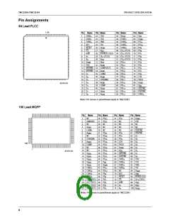
Pin Descriptions (continued)
Pin Number
84-Lead 100-Lead
Pin Name
Test
PLCC
MQFP
Value
Pin Function Description
TEST
28, 29,
48-51
22-25,
96-97
0.0 V
Factory testing (TMC22091 only). Reserved for factory
testing. These pins have no effect on the operation but do
function as JTAG registers. They should be grounded directly
or pulled down to ground with 1kΩ or smaller resistors.
NC
N/A
1, 3, 7,
11-12,
No Connect
28-30,
52-55,
69, 78-79
Control Registers
The TMC22x91 is initialized and controlled by a set of regis-
ters. The registers are organized into 13 categories:
contents or those of the Control Registers. The port is
governed by pins CS, R/W, and A
.
1-0
1. Global Control
2. Format Control
3. Interface Control
4. Test Control
The Address Register for the CLUT and the Control Register
pointer automatically increment to allow successive writes to
sequential addresses. In the CLUT, the Address Register has
two additional bits which increment in modulo-three to
sequentially access the red, green, and blue portions. All
three colors must be written when any CLUT address is
changed.
5. Key Control
6. Misc. Control
7. Standards Control
8. Layering Control (TMC22191)
9. Key Value
The control register autoincrement follows the sequence
indicated in the Control Register Map. When it reaches
address 40, it stops incrementing, allowing multiple reads or
writes of test data from/to the TESTDAT register. To exit the
test mode, reset the Control Register pointer by setting A
,
10. Timing
1-0
D , and R/W LOW and then bring CS LOW. Address 1F is
7-0
11. Subcarrier
a read-only status register. It is addressed by the autoincre-
ment sequencer. Any data may be written into this port at
that time but it will not be stored. When address 50 is
accessed, no autoincrement takes place, allowing multiple
writes to the Mask Register.
12. Test I/O
13. Mask Register
An external controller loads the Control Registers through a
standard interface port. It also loads the CLUT and reads its
10

 CADEKA [ CADEKA MICROCIRCUITS LLC. ]