Preliminary Datasheet
BOOST CONTROLLER
AP3039
Typical Application (Continued)
VIN : 6V to 27V
R1
CIN
COUT
L
D1
R3
VIN
UVLO
Q1
OUT
CS
CV
R2
VCC
EN
R4
7 *10
RCS
OFF ON
RT
OV
SHDN
FB
RT
CH 1
SHDN
CH 2
CH7
CH 8
EN
OFF ON
SS
CSS
COMP
FB
U2 AP3608
PWM
SDA
RC
CC
PWM
Dimming
GND
VCC
ISET
CIN2
0.1μF
SCL
SCE
PGND
AGND
U1 AP3039
Digital
Dimming
AP3608
CC=5.0V
External
V
C: X5R or X7R Dielectric
L: SUMIDA CDR6D28MN-220NC
Q1: FAIRCHILD FDC5612
D1: FAIRCHILD SS36
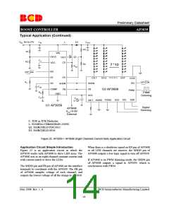
Figure 22. AP3039 + AP3608 (Eight Channels Current Sink) Application Circuit
Application Circuit Simple Introduction
Figure 22 is an application circuit in which the
AP3039 works with AP3608 to drive LED array. The
AP3608 acts as an eight-channel constant current sink
with current match to drive the LEDs.
When there is a shutdown signal on EN pin of AP3608
or all LED channels are inactive, the SHDN pin of
AP3608 outputs a low logic signal to turn off AP3039.
If AP3608 is on PWM dimming mode, the SHDN pin
of AP3608 outputs a signal to AP3039, which is
synchronous with PWM.
The SHDN pin and FB pin of AP3608 are the interface
terminals to coordinate with the AP3039. The FB pin
of AP3608 samples voltage of each channel, and
outputs the lowest voltage of all the strings to AP3039.
May 2008 Rev. 1. 0
BCD Semiconductor Manufacturing Limited
14

 BCDSEMI [ BCD SEMICONDUCTOR MANUFACTURING LIMITED ]