THEORY OF OPERATION
ADVANCED SIGN MAGNITUDE
DISCUSSION OF
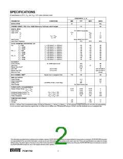
SPECIFICATIONS
Digital audio systems have traditionally used laser-trimmed,
current-source DACs in order to achieve sufficient accuracy.
However, even the best of these suffer from potential low-
level nonlinearity due to errors at the major carry bipolar
zero transition. More recently, DACs employing a different
architecture which utilizes noise shaping techniques and
very high over-sampling frequencies, have been introduced
(“Bitstream”, “MASH”, or 1-bit DAC). These DACs over-
come the low level linearity problem, but only at the expense
of signal-to-noise performance, and often to the detriment of
channel separation and intermodulation distortion if the
succeeding circuitry is not carefully designed.
DYNAMIC SPECIFICATIONS
Total Harmonic Distortion + Noise
The key specifications for the PCM1702 is total harmonic
distortion plus noise (THD+N).
Digital data words are read into the PCM1702 at eight times
the standard compact disk audio sampling frequency of
44.1kHz (352.8kHz) so that a sine wave output of 1002Hz
is realized.
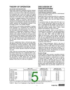
For production testing, the output of the DAC goes to an
I to V converter, then through a 40kHz low pass filter, and
then to a programmable gain amplifier to provide gain at
lower signal output test levels before being fed into an
analog-type distortion analyzer. Figure 1 shows a block
diagram of the production THD+N test setup.
The PCM1702 is a new solution to the problem. It combines
all the advantages of a conventional DAC (excellent full
scale performance, high signal-to-noise ratio and ease of
use) with superior low-level performance. Two DACs are
combined in a complementary arrangement to produce an
extremely linear output. The two DACs share a common
reference, and a common R-2R ladder for bit current sources
by dual balanced current segments to ensure perfect tracking
under all conditions. By interleaving the individual bits of
each DAC and employing precise laser trimming of resis-
tors, the highly accurate match required between DACs is
achieved.
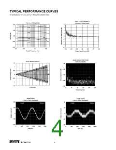
For the audio bandwidth, THD+N of the PCM1702 is
essentially flat for all frequencies. The typical performance
curve, “THD+N vs Frequency”, shows four different output
signal levels: 0dB, –20dB, –40dB, and –60dB. The test
signals are derived from a special compact test disk (the
CBS CD-1). It is interesting to note that the –20dB signal
falls only about 10dB below the full scale signal instead of
the expected 20dB. This is primarily due to the superior low
level signal performance of the advanced sign magnitude
architecture of the PCM1702.
This new, complementary linear or advanced sign magni-
tude approach, which steps away from zero with small steps
in both directions, avoids any glitching or “large” linearity
errors and provides an absolute current output. The low level
performance of the PCM1702 is such that real 20-bit reso-
lution can be realized, especially around the critical bipolar
zero point.
In terms of signal measurement, THD+N is the ratio of
DistortionRMS + NoiseRMS/ SignalRMS expressed in dB. For the
PCM1702, THD+N is 100% tested at all three specified
output levels using the test setup shown in Figure 1. It is
significant to note that this test setup does not include any
output deglitching circuitry. All specifications are achieved
without the use of external deglitchers.
Table 1 shows the conversion made by the internal logic of
the PCM1702 from binary two’s complement (BTC). Also,
the resulting internal codes to the upper and lower DACs
(see front page block diagram) are listed. Notice that only
the LSB portions of either internal DAC are changing
around bipolar zero. This accounts for the superlative per-
formance of the PCM1702 in this area of operation.
Dynamic Range
Dynamic range in audio converters is specified as the mea-
sure of THD+N at an effective output signal level of –60dB
referred to 0dB. Resolution is commonly used as a theoreti-
cal measure of dynamic range, but it does not take into
account the effects of distortion and noise at low signal
levels. The advanced sign magnitude architecture of the
PCM1702, with its ideal performance around bipolar zero,
provides a more usable dynamic range, even using the strict
audio definition, than any previously available D/A con-
verter.
INPUT CODE
LOWER DAC CODE
UPPER DAC CODE
ANALOG OUTPUT
(20-bit Binary Two's Complement)
(19-bit Straight Binary)
(19-bit Straight Binary)
+Full Scale
011...111
011...110
000...010
000...001
000...000
111...111
111...110
100...001
100...000
111...111+1LSB(1)
111...111+1LSB(1)
111...111+1LSB(1)
111...111+1LSB(1)
111...111+1LSB(1)
111...111
111...111
111...110
000...010
000...001
000...000
000...000
000...000
000...000
000...000
+Full Scale –1LSB
Bipolar Zero +2LSB
Bipolar Zero +1LSB
Bipolar Zero
Bipolar Zero –1LSB
Bipolar Zero –2LSB
–Full Scale +LSB
–Full Scale
111...110
000...001
000...000
NOTE: (1) The extra weight of 1LSB is added at this point to make the transfer function symmetrical around bipolar zero.
TABLE I. Binary Two's Complement to Sign Magnitude Conversion Chart.
®
5
PCM1702

 BB [ BURR-BROWN CORPORATION ]