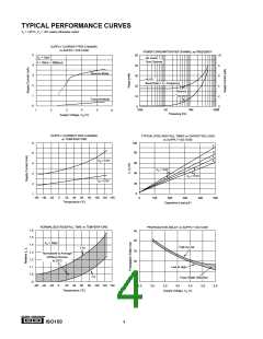
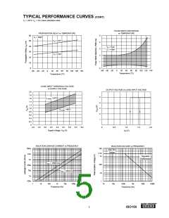
TYPICAL PERFORMANCE CURVES (CONT)
TA = +25°C, VS = +5V unless otherwise noted.
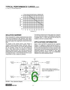
TYPICAL INSULATION RESISTANCE vs TEMPERATURE
1016
1015
1014
1013
1012
1011
1010
0
20
40
60
80 100 120 140 160 180
Temperature (°C)
Conventional isolation barrier testing applies test voltage far
ISOLATION BARRIER
in excess of the rated voltage to catastrophically break down
a marginal device. A device that passes the test may be
weakened, and lead to premature failure.
Data is transmitted by coupling complementary logic pulses
to the receiver through two 0.4pF capacitors. These capaci-
tors are built into the ISO150 package with Faraday shield-
ing to guard against false triggering by external electrostatic
fields.
APPLICATIONS INFORMATION
The integrity of the isolation barrier of the ISO150 is
verified by partial discharge testing. 2400Vrms, 60Hz, is
applied across the barrier for one second while measuring
any tiny discharge currents that may flow through the
barrier. These current pulses are produced by localized
ionization within the barrier. This is the most sensitive and
reliable indicator of barrier integrity and longevity, and does
not damage the barrier. A device fails the test if five or more
current pulses of 5pC or greater are detected.
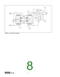
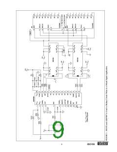
Figure 1 shows the ISO150 connected for basic operation.
Channel 1 is configured to transmit data from side B to A.
Channel 2 is set for transmission from side A to B. The R/T pins
for each of the four transceivers are shown connected to the
required logic level for the transmission direction shown. The
transmission direction can be controlled by logic signals
applied to the R/T pins. Channel 1 and 2 can be independently
controlled for the desired transmission direction.
+5V(1)
(Receive)
(Transmit)
Channel 2
(2)
Channel 2
Data Out
(1)
(1)
Data In
D2A
GA
VSB
D2B
R/T2A
R/T2B
Channel 2
NOTES: (1) Power Supplies and grounds on
side A and side B are isolated. (2) Recommended
bypass: 0.1µF in parallel with 1nF.
Side A
Side B
Channel 1
D1A
VSA
GB
D1B
R/T1A
R/T1B
(2)
Channel 1
Data Out
Channel 1
Data In
(Receive)
+5V(1)
(Transmit)
(1)
(1)
FIGURE 1. Basic Operation Diagram.
®
ISO150
6

 BB [ BURR-BROWN CORPORATION ]