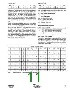
Address Byte
Command Byte
MSB
1
6
0
5
0
4
1
3
0
2
1
LSB
R/W
MSB
SD
6
5
4
3
2
1
LSB
X
A1
A0
C2
C1
C0
PD1
PD0
X
The address byte is the first byte received following the
START condition from the master device. The first five bits
(MSBs) of the slave address are factory pre-set to 10010.
The next two bits of the address byte are the device select
bits, A1 and A0. Input pins (A1-A0) on the ADS7830 deter-
mine these two bits of the device address for a particular
ADS7830. A maximum of four devices with the same pre-set
code can therefore be connected on the same bus at one
time.
The ADS7830’s operating mode is determined by a com-
mand byte which is illustrated above.
SD: Single-Ended/Differential Inputs
0: Differential Inputs
1: Single-Ended Inputs
C2 - C0: Channel Selections
PD1 - 0: Power-Down Selection
X: Unused
See Table I for Truth Table.
The A1-A0 Address Inputs can be connected to VDD or digital
ground. The device address is set by the state of these pins
upon power-up of the ADS7830.
POWER-DOWN SELECTION
The last bit of the address byte (R/W) defines the operation
to be performed. When set to a “1” a read operation is
selected; when set to a “0” a write operation is selected.
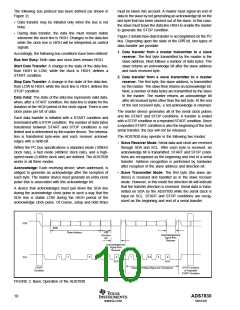
Following the START condition the ADS7830 monitors the
SDA bus, checking the device type identifier being transmit-
ted. Upon receiving the 10010 code, the appropriate device
select bits, and the R/W bit, the slave device outputs an
acknowledge signal on the SDA line.
PD1 PD0
DESCRIPTION
0
0
1
1
0
1
0
1
Power Down Between A/D Converter Conversions
Internal Reference OFF and A/D Converter ON
Internal Reference ON and A/D Converter OFF
Internal Reference ON and A/D Converter ON
INITIATING CONVERSION
Provided the master has write-addressed it, the ADS7830
turns on the A/D converter’s section and begins conversions
when it receives BIT 4 of the command byte shown in the
Command Byte. If the command byte is correct, the ADS7830
will return an ACK condition.
CHANNEL SELECTION CONTROL
SD
0
0
0
0
0
0
0
0
1
1
1
1
1
1
1
1
C2
0
0
0
0
1
1
1
1
0
0
0
0
1
1
1
1
C1
0
0
1
1
0
0
1
1
0
0
1
1
0
0
1
1
C0
0
1
0
1
0
1
0
1
0
1
0
1
0
1
0
1
CH0
+IN
—
CH1
–IN
—
CH2
—
CH3
—
CH4
—
CH5
—
CH6
—
CH7
—
COM
—
+IN
—
–IN
—
—
—
—
—
—
—
—
+IN
—
–IN
—
—
—
—
—
—
—
—
+IN
—
–IN
—
—
–IN
—
+IN
—
—
—
—
—
—
–IN
—
+IN
—
—
—
—
—
—
—
—
–IN
—
+IN
—
—
—
—
—
—
—
—
–IN
—
+IN
—
—
+IN
—
—
—
—
—
—
–IN
–IN
–IN
–IN
–IN
–IN
–IN
–IN
—
+IN
—
—
—
—
—
—
—
—
—
+IN
—
—
—
—
—
—
—
—
—
+IN
—
—
—
+IN
—
—
—
—
—
—
—
—
+IN
—
—
—
—
—
—
—
—
—
+IN
—
—
—
—
—
—
—
—
—
+IN
TABLE I. Channel Selection Control Addressed by Command BYTE.
ADS7830
11
www.ti.com
SBAS302

 BB [ BURR-BROWN CORPORATION ]