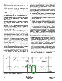
The following bus protocol has been defined (as shown in
Figure 2):
must be taken into account. A master must signal an end of
data to the slave by not generating an acknowledge bit on the
last byte that has been clocked out of the slave. In this case,
the slave must leave the data line HIGH to enable the master
to generate the STOP condition.
• Data transfer may be initiated only when the bus is not
busy.
• During data transfer, the data line must remain stable
whenever the clock line is HIGH. Changes in the data line
while the clock line is HIGH will be interpreted as control
signals.
Figure 2 details how data transfer is accomplished on the I2C
bus. Depending upon the state of the R/W bit, two types of
data transfer are possible:
1. Data transfer from a master transmitter to a slave
receiver. The first byte transmitted by the master is the
slave address. Next follows a number of data bytes. The
slave returns an acknowledge bit after the slave address
and each received byte.
Accordingly, the following bus conditions have been defined:
Bus Not Busy: Both data and clock lines remain HIGH.
Start Data Transfer: A change in the state of the data line,
from HIGH to LOW, while the clock is HIGH, defines a
START condition.
2. Data transfer from a slave transmitter to a master
receiver. The first byte, the slave address, is transmitted
by the master. The slave then returns an acknowledge bit.
Next, a number of data bytes are transmitted by the slave
to the master. The master returns an acknowledge bit
after all received bytes other than the last byte. At the end
of the last received byte, a not-acknowledge is returned.
Stop Data Transfer: A change in the state of the data line,
from LOW to HIGH, while the clock line is HIGH, defines the
STOP condition.
Data Valid: The state of the data line represents valid data,
when, after a START condition, the data line is stable for the
duration of the HIGH period of the clock signal. There is one
clock pulse per bit of data.
The master device generates all of the serial clock pulses
and the START and STOP conditions. A transfer is ended
with a STOP condition or a repeated START condition. Since
a repeated START condition is also the beginning of the next
serial transfer, the bus will not be released.
Each data transfer is initiated with a START condition and
terminated with a STOP condition. The number of data bytes
transferred between START and STOP conditions is not
limited and is determined by the master device. The informa-
tion is transferred byte-wise and each receiver acknowl-
edges with a ninth-bit.
The ADS7830 may operate in the following two modes:
• Slave Receiver Mode: Serial data and clock are received
through SDA and SCL. After each byte is received, an
acknowledge bit is transmitted. START and STOP condi-
tions are recognized as the beginning and end of a serial
transfer. Address recognition is performed by hardware
after reception of the slave address and direction bit.
Within the I2C bus specifications a standard mode (100kHz
clock rate), a fast mode (400kHz clock rate), and a high-
speed mode (3.4MHz clock rate) are defined. The ADS7830
works in all three modes.
Acknowledge: Each receiving device, when addressed, is
obliged to generate an acknowledge after the reception of
each byte. The master device must generate an extra clock
pulse that is associated with this acknowledge bit.
• Slave Transmitter Mode: The first byte (the slave ad-
dress) is received and handled as in the slave receiver
mode. However, in this mode the direction bit will indicate
that the transfer direction is reversed. Serial data is trans-
mitted on SDA by the ADS7830 while the serial clock is
input on SCL. START and STOP conditions are recog-
nized as the beginning and end of a serial transfer.
A device that acknowledges must pull down the SDA line
during the acknowledge clock pulse in such a way that the
SDA line is stable LOW during the HIGH period of the
acknowledge clock pulse. Of course, setup and hold times
SDA
MSB
Slave Address
R/W
Direction
Bit
Acknowledgement
Signal from
Receiver
Acknowledgement
Signal from
Receiver
1
2
6
7
8
9
1
2
3-8
8
9
SCL
ACK
ACK
START
Condition
STOP Condition
or Repeated
Repeated If More Bytes Are Transferred
START Condition
FIGURE 2. Basic Operation of the ADS7830.
ADS7830
SBAS302
10
www.ti.com

 BB [ BURR-BROWN CORPORATION ]