General Description
Effects of Voltage – Variations in voltage have little effect
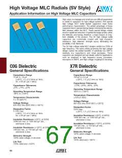
on Class 1 dielectric but does affect the capacitance and
dissipation factor of Class 2 dielectrics. The application of
DC voltage reduces both the capacitance and dissipation
factor while the application of an AC voltage within a
reasonable range tends to increase both capacitance and
dissipation factor readings. If a high enough AC voltage is
applied, eventually it will reduce capacitance just as a DC
voltage will. Figure 2 shows the effects of AC voltage.
Table 1: EIA and MIL Temperature Stable and General
Application Codes
EIA CODE
Percent Capacity Change Over Temperature Range
RS198
Temperature Range
X7
X5
Y5
Z5
-55°C to +125°C
-55°C to +85°C
-30°C to +85°C
+10°C to +85°C
Cap. Change vs. A.C. Volts
X7R
Code
Percent Capacity Change
50
40
30
20
D
E
F
P
R
S
T
3.3ꢀ
4.7ꢀ
7.5ꢀ
10ꢀ
15ꢀ
22ꢀ
+22ꢀ, -33ꢀ
+22ꢀ, - 56ꢀ
+22ꢀ, -82ꢀ
10
0
U
V
EXAMPLE – A capacitor is desired with the capacitance value at 25°C
to increase no more than 7.5ꢀ or decrease no more than 7.5ꢀ from
-30°C to +85°C. EIA Code will be Y5F.
12.5
25
37.5
50
Volts AC at 1.0 KHz
Figure 2
MIL CODE
Capacitor specifications specify the AC voltage at which to
measure (normally 0.5 or 1 VAC) and application of the
wrong voltage can cause spurious readings.
Symbol
Temperature Range
A
B
C
-55°C to +85°C
-55°C to +125°C
-55°C to +150°C
Typical Cap. Change vs. Temperature
X7R
Cap. Change
Zero Volts
Cap. Change
Rated Volts
Symbol
+20
Q
R
W
X
+15ꢀ, -15ꢀ
+15ꢀ, -15ꢀ
+22ꢀ, -56ꢀ
+15ꢀ, -15ꢀ
+30ꢀ, -70ꢀ
+20ꢀ, -20ꢀ
+15ꢀ, -50ꢀ
+15ꢀ, -40ꢀ
+22ꢀ, -66ꢀ
+15ꢀ, -25ꢀ
+30ꢀ, -80ꢀ
+20ꢀ, -30ꢀ
+10
0VDC
0
-10
-20
Y
Z
Temperature characteristic is specified by combining range and change
symbols, for example BR or AW. Specification slash sheets indicate the
characteristic applicable to a given style of capacitor.
-30
-55 -35 -15 +5 +25 +45 +65 +85 +105 +125
Temperature Degrees Centigrade
In specifying capacitance change with temperature for Class
2 materials, EIA expresses the capacitance change over an
operating temperature range by a 3 symbol code. The
first symbol represents the cold temperature end of the
temperature range, the second represents the upper limit of
the operating temperature range and the third symbol repre-
sents the capacitance change allowed over the operating
temperature range. Table 1 provides a detailed explanation of
the EIA system.
Figure 3
70

 KYOCERA AVX [ KYOCERA AVX ]