T5743
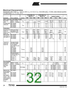
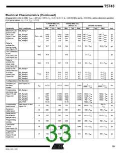
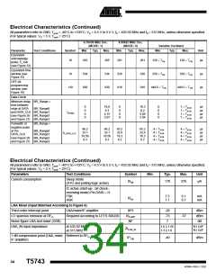
Electrical Characteristics (Continued)
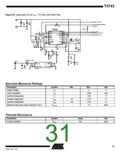
All parameters refer to GND, Tamb = -40LC to +105LC, VS = 4.5 V to 5.5 V, f0 = 433.92 MHz and f0 = 315 MHz, unless otherwise specified.
(For typical values: VS = 5 V, Tamb = 25LC)
Parameters
Test Conditions
Symbol
Min.
Typ.
Max.
Unit
Maximum input level
BER ? 10-3,
FSK mode
ASK mode
Pin_max
-22
-20
dBm
dBm
Local Oscillator
Operating frequency range VCO
Phase noise VCO/LO
fVCO
299
449
MHz
fosc = 432.92 MHz
at 1 MHz
at 10 MHz
L (fm)
-93
-113
-90
-110
dBC/Hz
dBC/Hz
Spurious of the VCO
VCO gain
at ± fXTO
-55
-47
dBC
KVCO
190
MHz/V
Loop bandwidth of the PLL
For best LO noise (design
parameter)
R1 = 820 ꢃ
C9 = 4.7 nF
C10 = 1 nF
BLoop
100
kHz
nF
Capacitive load at Pin LF
XTO operating frequency
The capacitive load at Pin LF is
limited if bit check is used. The
limitation therefore also applies to
self polling.
CLF_tot
10
XTO crystal frequency, appropriate
load capacitance must be connected
to XTAL
fXTAL = 6.764375 MHz (EU)
fXTO
-30 ppm
fXTAL
+30 ppm
MHz
fXTAL = 4.90625 MHz (US)
Series resonance resistor of the
crystal
f
f
XTO = 6.764 MHz,
XTO = 4.906 MHz
150
220
ꢃ
ꢃ
RS
C0
Static capacitance at Pin XTO to
GND
6.5
pF
Analog Signal Processing
Input sensitivity ASK
300 kHz IF-filter
Input matched according to
Figure 6
ASK (level of carrier)
BER ? 10-3, BW = 300 kHz
fin = 433.92 MHz/315 MHz
VS = 5 V, Tamb = 25LC, fIF = 1 MHz
BR_Range0
BR_Range1
BR_Range2
BR_Range3
PRef_ASK
-109
-107
-106
-104
-111
-109
-108
-106
-113
-111
-110
-108
dBm
dBm
dBm
dBm
35
4569A–RKE–12/02

 ATMEL [ ATMEL ]