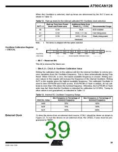
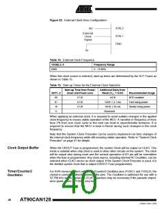
Figure 22. External Clock Drive Configuration
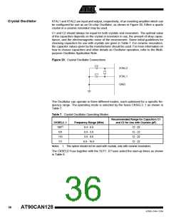
XTAL2
XTAL1
GND
NC
External
Clock
Signal
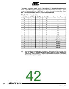
Table 14. External Clock Frequency
CKSEL3..0
Frequency Range
0 - 16 MHz
0000
When this clock source is selected, start-up times are determined by the SUT Fuses as
shown in Table 15.
Table 15. Start-up Times for the External Clock Selection
Start-up Time from Power-
down and Power-save
Additional Delay from
Reset (VCC = 5.0V)
SUT1..0
00
Recommended Usage
BOD enabled
6 CK
6 CK
6 CK
14CK
01
14CK + 4.1 ms
14CK + 65 ms
Reserved
Fast rising power
Slowly rising power
10
11
When applying an external clock, it is required to avoid sudden changes in the applied
clock frequency to ensure stable operation of the MCU. A variation in frequency of more
than 2% from one clock cycle to the next can lead to unpredictable behavior. It is
required to ensure that the MCU is kept in Reset during such changes in the clock
frequency.
Note that the System Clock Prescaler can be used to implement run-time changes of
the internal clock frequency while still ensuring stable operation. Refer to “System Clock
Prescaler” on page 41 for details.
Clock Output Buffer
When the CKOUT Fuse is programmed, the system Clock will be output on CLKO. This
mode is suitable when chip clock is used to drive other circuits on the system. The clock
will be output also during reset and the normal operation of I/O pin will be overridden
when the fuse is programmed. Any clock source, including internal RC Oscillator, can be
selected when CLKO serves as clock output. If the System Clock Prescaler is used, it is
the divided system clock that is output (CKOUT Fuse programmed).
Timer/Counter2
Oscillator
For AVR microcontrollers with Timer/Counter2 Oscillator pins (TOSC1 and TOSC2), the
crystal is connected directly between the pins. The Oscillator is optimized for use with a
32.768 kHz watch crystal. 12-22 pF capacitors may be necessary if the parasitic imped-
ance (pads, wires & PCB) is very low.
40
AT90CAN128
4250E–CAN–12/04

 ATMEL [ ATMEL ]