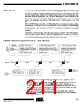
Transmission Modes
The TWI can operate in one of four major modes. These are named Master Transmitter
(MT), Master Receiver (MR), Slave Transmitter (ST) and Slave Receiver (SR). Several
of these modes can be used in the same application. As an example, the TWI can use
MT mode to write data into a TWI EEPROM, MR mode to read the data back from the
EEPROM. If other masters are present in the system, some of these might transmit data
to the TWI, and then SR mode would be used. It is the application software that decides
which modes are legal.
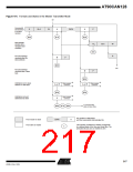
The following sections describe each of these modes. Possible status codes are
described along with figures detailing data transmission in each of the modes. These fig-
ures contain the following abbreviations:
S: START condition
Rs: REPEATED START condition
R: Read bit (high level at SDA)
W: Write bit (low level at SDA)
A: Acknowledge bit (low level at SDA)
A: Not acknowledge bit (high level at SDA)
Data: 8-bit data byte
P: STOP condition
SLA: Slave Address
In Figure 101 to Figure 107, circles are used to indicate that the TWINT flag is set. The
numbers in the circles show the status code held in TWSR, with the prescaler bits
masked to zero. At these points, actions must be taken by the application to continue or
complete the TWI transfer. The TWI transfer is suspended until the TWINT flag is
cleared by software.
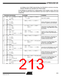
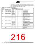
When the TWINT flag is set, the status code in TWSR is used to determine the appropri-
ate software action. For each status code, the required software action and details of the
following serial transfer are given in Table 90 to Table 93. Note that the prescaler bits
are masked to zero in these tables.
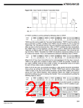
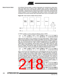
Master Transmitter Mode
In the Master Transmitter mode, a number of data bytes are transmitted to a slave
receiver (see Figure 100). In order to enter a Master mode, a START condition must be
transmitted. The format of the following address packet determines whether Master
Transmitter or Master Receiver mode is to be entered. If SLA+W is transmitted, MT
mode is entered, if SLA+R is transmitted, MR mode is entered. All the status codes
mentioned in this section assume that the prescaler bits are zero or are masked to zero.
214
AT90CAN128
4250E–CAN–12/04

 ATMEL [ ATMEL ]