AT90CAN128
Using the TWI
The AVR TWI is byte-oriented and interrupt based. Interrupts are issued after all bus
events, like reception of a byte or transmission of a START condition. Because the TWI
is interrupt-based, the application software is free to carry on other operations during a
TWI byte transfer. Note that the TWI Interrupt Enable (TWIE) bit in TWCR together with
the Global Interrupt Enable bit in SREG allow the application to decide whether or not
assertion of the TWINT flag should generate an interrupt request. If the TWIE bit is
cleared, the application must poll the TWINT flag in order to detect actions on the TWI
bus.
When the TWINT flag is asserted, the TWI has finished an operation and awaits applica-
tion response. In this case, the TWI Status Register (TWSR) contains a value indicating
the current state of the TWI bus. The application software can then decide how the TWI
should behave in the next TWI bus cycle by manipulating the TWCR and TWDR
Registers.
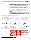
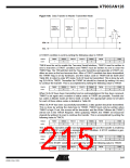
Figure 99 is a simple example of how the application can interface to the TWI hardware.
In this example, a master wishes to transmit a single data byte to a slave. This descrip-
tion is quite abstract, a more detailed explanation follows later in this section. A simple
code example implementing the desired behaviour is also presented.
Figure 99. Interfacing the Application to the TWI in a Typical Transmission
1. Application
writes to TWCR
to initiate
transmission of
START
3. Check TWSR to see if
5. Check TWSR to see if SLA+W
was sent and ACK received.
Application loads data into TWDR,
and loads appropriate control signals
into TWCR, making sure that TWINT
is written to one.
7. Check TWSR to see if data
was sent and ACK received.
Application loads appropriate
control signals to send STOP
into TWCR, making sure that
TWINT is written to one
START was sent. Application
loads SLA+W into TWDR, and
loads appropriate control signals
into TWCR, making sure that
TWINT is written to one.
TWI bus
START
SLA+W
A
Data
A
STOP
Indicates
TWINT set
2. TWINT set.
Status code indicates
START condition sent
4. TWINT set.
6. TWINT set.
Status code indicates
data sent, ACK received
Status code indicates
SLA+W sendt, ACK
received
TWI
Hardware
Action
1. The first step in a TWI transmission is to transmit a START condition. This is
done by writing a specific value into TWCR, instructing the TWI hardware to
transmit a START condition. Which value to write is described later on. However,
it is important that the TWINT bit is set in the value written. Writing a one to
TWINT clears the flag. The TWI will not start any operation as long as the TWINT
bit in TWCR is set. Immediately after the application has cleared TWINT, the TWI
will initiate transmission of the START condition.
2. When the START condition has been transmitted, the TWINT flag in TWCR is
set, and TWSR is updated with a status code indicating that the START condition
has successfully been sent.
211
4250E–CAN–12/04

 ATMEL [ ATMEL ]