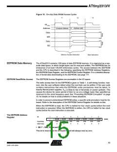
• Bits 6..0 – EEAR6..0: EEPROM Address
The EEPROM Address Register – EEAR specify the EEPROM address in the 128 bytes
EEPROM space. The EEPROM data bytes are addressed linearly between 0 and 127.
The initial value of EEAR is undefined. A proper value must be written before the
EEPROM may be accessed.
The EEPROM Data Register –
EEDR
Bit
7
6
5
4
3
2
1
0
MSB
R/W
0
LSB
R/W
0
EEDR
Read/Write
Initial Value
R/W
0
R/W
0
R/W
0
R/W
0
R/W
0
R/W
0
• Bits 7..0 – EEDR7..0: EEPROM Data
For the EEPROM write operation, the EEDR Register contains the data to be written to
the EEPROM in the address given by the EEAR Register. For the EEPROM read oper-
ation, the EEDR contains the data read out from the EEPROM at the address given by
EEAR.
The EEPROM Control Register
– EECR
Bit
7
–
6
–
5
EEPM1
R/W
X
4
EEPM0
R/W
X
3
EERIE
R/W
0
2
EEMPE
R/W
0
1
EEPE
R/W
X
0
EERE
R/W
0
EECR
Read/Write
Initial Value
R
0
R
0
• Bits 7..6 – Res: Reserved Bits
These bits are reserved bits in the ATtiny2313 and will always read as zero.
• Bits 5, 4 – EEPM1 and EEPM0: EEPROM Programming Mode Bits
The EEPROM Programming mode bits setting defines which programming action that
will be triggered when writing EEPE. It is possible to program data in one atomic opera-
tion (erase the old value and program the new value) or to split the Erase and Write
operations in two different operations. The Programming times for the different modes
are shown in Table 1. While EEPE is set, any write to EEPMn will be ignored. During
reset, the EEPMn bits will be reset to 0b00 unless the EEPROM is busy programming.
Table 1. EEPROM Mode Bits
Programming
EEPM1 EEPM0
Time
3.4 ms
1.8 ms
1.8 ms
–
Operation
0
0
1
1
0
1
0
1
Erase and Write in one operation (Atomic Operation)
Erase Only
Write Only
Reserved for future use
• Bit 3 – EERIE: EEPROM Ready Interrupt Enable
Writing EERIE to one enables the EEPROM Ready Interrupt if the I-bit in SREG is set.
Writing EERIE to zero disables the interrupt. The EEPROM Ready Interrupt generates a
constant interrupt when Non-volatile memory is ready for programming.
16
ATtiny2313/V
2543F–AVR–08/04

 ATMEL [ ATMEL ]