ATmega64A
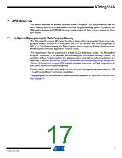
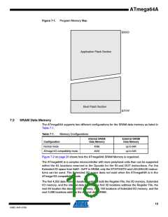
Figure 7-1. Program Memory Map
$0000
Application Flash Section
Boot Flash Section
$7FFF
7.2
SRAM Data Memory
The ATmega64A supports two different configurations for the SRAM data memory as listed in
Table 7-1.
Table 7-1.
Memory Configurations
Internal SRAM
Data Memory
External SRAM
Data Memory
Configuration
Normal mode
4096
4000
up to 64K
up to 64K
ATmega103 compatibility mode
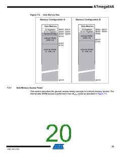
Figure 7-2 on page 20 shows how the ATmega64A SRAM Memory is organized.
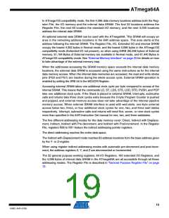
The ATmega64A is a complex microcontroller with more peripheral units than can be supported
within the 64 locations reserved in the Opcode for the IN and OUT instructions. For the
Extended I/O space from 0x60 - 0xFF in SRAM, only the ST/STS/STD and LD/LDS/LDD instruc-
tions can be used. The Extended I/O space does not exist when the ATmega64A is in the
ATmega103 compatibility mode.
The first 4,352 data memory locations address both the Register File, the I/O memory, Extended
I/O memory, and the internal data SRAM. The first 32 locations address the Register File, the
next 64 location the standard I/O memory, then 160 locations of Extended I/O memory, and the
next 4,096 locations address the internal data SRAM.
18
8160C–AVR–07/09

 ATMEL [ ATMEL ]