ATmega48PA/88PA/168PA/328P
18.3 SS Pin Functionality
18.3.1
Slave Mode
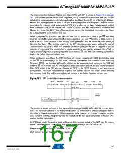
When the SPI is configured as a Slave, the Slave Select (SS) pin is always input. When SS is
held low, the SPI is activated, and MISO becomes an output if configured so by the user. All
other pins are inputs. When SS is driven high, all pins are inputs, and the SPI is passive, which
means that it will not receive incoming data. Note that the SPI logic will be reset once the SS pin
is driven high.
The SS pin is useful for packet/byte synchronization to keep the slave bit counter synchronous
with the master clock generator. When the SS pin is driven high, the SPI slave will immediately
reset the send and receive logic, and drop any partially received data in the Shift Register.
18.3.2
Master Mode
When the SPI is configured as a Master (MSTR in SPCR is set), the user can determine the
direction of the SS pin.
If SS is configured as an output, the pin is a general output pin which does not affect the SPI
system. Typically, the pin will be driving the SS pin of the SPI Slave.
If SS is configured as an input, it must be held high to ensure Master SPI operation. If the SS pin
is driven low by peripheral circuitry when the SPI is configured as a Master with the SS pin
defined as an input, the SPI system interprets this as another master selecting the SPI as a
slave and starting to send data to it. To avoid bus contention, the SPI system takes the following
actions:
1. The MSTR bit in SPCR is cleared and the SPI system becomes a Slave. As a result of
the SPI becoming a Slave, the MOSI and SCK pins become inputs.
2. The SPIF Flag in SPSR is set, and if the SPI interrupt is enabled, and the I-bit in SREG is
set, the interrupt routine will be executed.
Thus, when interrupt-driven SPI transmission is used in Master mode, and there exists a possi-
bility that SS is driven low, the interrupt should always check that the MSTR bit is still set. If the
MSTR bit has been cleared by a slave select, it must be set by the user to re-enable SPI Master
mode.
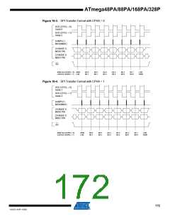
18.4 Data Modes
There are four combinations of SCK phase and polarity with respect to serial data, which are
determined by control bits CPHA and CPOL. The SPI data transfer formats are shown in Figure
18-3 and Figure 18-4 on page 172. Data bits are shifted out and latched in on opposite edges of
the SCK signal, ensuring sufficient time for data signals to stabilize. This is clearly seen by sum-
marizing Table 18-3 on page 173 and Table 18-4 on page 173, as done in Table 18-2.
Table 18-2. SPI Modes
SPI Mode
Conditions
Leading Edge
Sample (Rising)
Setup (Rising)
Sample (Falling)
Setup (Falling)
Trailing eDge
Setup (Falling)
Sample (Falling)
Setup (Rising)
Sample (Rising)
0
1
2
3
CPOL=0, CPHA=0
CPOL=0, CPHA=1
CPOL=1, CPHA=0
CPOL=1, CPHA=1
171
8161D–AVR–10/09

 ATMEL [ ATMEL ]